
Version history
This document remains the property of DSBJV. Its contents are confidential and shall not be reproduced, destroyed or given away without express, written permission of DSBJV. The electronic version of this document in FULCRUM on designated serves(s) is the Master Copy and is a controlled document. Unless specifically noted, thereon, other copies of this document are uncontrolled.
p:\30850\30850.0500 planning\30850.0512 (erosion and sediment)\issueddocuments\annual review 2017\crl-btm-env-dow-pln-000344 updated ctmp rev 6.docx
Glossary of terms
Term Definition
ACZ Active Construction Zone
AC Auckland Council
ANZECC Australian and New Zealand Environment Conservation Council
ARI Annual Return Interval
AT Auckland Transport
BTC Britomart Transport Centre
CEMP Construction Environmental Management Plan
CPO Former Chief Post Office building
CRL City Rail Link
CRLL City Rail Link Limited
CSA Construction Support Area
CTMP Chemical Treatment Management Plan
CTP Chemical Treatment Plant
DSBJV Downer Soletanche Bachy Joint Venture
ECBF East Coast Bays Formation
ESCP Erosion and Sediment Control Plan
ESRP Emergency Spill Response Plan
ITA EMP Industrial and Trade Activities Environmental Management Plan
PAC Polyaluminium Chloride
TPH Total Petroleum Hydrocarbons
TSS Total Suspended Solids
1 Introduction
The City Rail Link (CRL) project comprises the construction, operation and maintenance of a 3.4 km underground passenger railway, running between Britomart Station and the North Auckland Rail Line in the vicinity of Mt Eden station. The works relating to this Chemical Treatment Management Plan (CTMP) constitute part of the enabling works for the CRL.
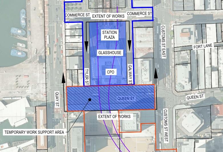
The works (the Project) involve the construction of an extension to the existing passenger rail network from the current termination point within the Britomart Transport Centre (BTC), westwards underneath the former Chief Post Office building (CPO) and Lower Queen Street. The Project footprint is shown generally by the blue shaded area in Figure 1.1 below.
Further details on the Project description, Active Construction Zones (ACZ), Construction Support Areas (CSA) and physical works are set out in Section 2 of the Erosion and Sediment Control Plan (ESCP).
1.1 Sediment laden water
LEGEND
CRL alignment
BTC designation
CRL designation
C1 worksite
It is expected that sediment laden water will be generated during construction of the Project. Most of the water will be generated within ACZ D during Stage 3 of the work - cut and cover excavations in Lower Queen Street (refer Section 2.4 of the ESCP). The majority of Stages 1, 2 and 4 (works with ACZ A, B and C) will predominantly be undertaken under roof, with no, or very limited rainfall contribution
A settlement based treatment plant will be located on-site within CSA A, adjacent to the south east corner of the CPO building and next to the glasshouse. The treatment plant is a key component of the erosion and sediment control measures to be implemented for the Project as outlined in the ESCP. The treatment plant will remove sediment from contaminated water generated from the excavation works in order to achieve an acceptable water quality for discharge into the stormwater system. Assisted settlement (through use of a flocculant) may be required at times for the removal of small particles, such as fine silt and clay. The treatment plant will include capability to assist the settlement process with the use of flocculant when required.
Figure 1 1: Project Footprint
Bench tests have been conducted on soil samples taken from cored material retrieved from a site investigation borehole drilled within the Project area in May 2016 (refer to Figure 1 in Appendix D of the ESCP for the borehole location). The tests have confirmed that chemical treatment is required to assist the settlement process A copy of the report on the bench testing, conducted by IXOM (formerly, Orica), is included in Appendix A of this report
The treatment plant, including the chemical treatment facility, is hereafter referred to as the chemical treatment plant (CTP).
This CTMP has been prepared by Tonkin & Taylor Ltd (T+T) for the Downer Soletanche Bachy Joint Venture (the Contractor – DSBJV) and forms part of the Construction Environmental Management Plan (CEMP) for the Project.
1.2 Purpose of the Chemical Treatment Management Plan
This CTMP is required under Condition 50 of the CRL Britomart to Wyndham Street land use consent R/REG/2014/5430 and Conditions 99 to 104 of discharge permit R/REG/2014/5436.
This CTMP outlines:
• Specific design details of the chemical treatment system, including details of the optimum dosage;
• Water discharge quality;
• Monitoring, maintenance and contingency programme;
• Results of initial chemical treatment trial;
• Spill contingency plan; and
• Responsibilities for the long term operation and maintenance of the chemical treatment system.
1.3
Relevant Conditions
Table 1 1 outlines the resource consent conditions relevant to this CTMP and where they are addressed in the document.
Table 1.1: CTMP resource consent conditions
Condition No.
Condition
Land Use Consent R/REG/2014/5430
Chemical Treatment Management Plan (“CTMP”)
Relevant section of the CTMP
50 At least 20 working days prior to the commencement of construction, a CTMP which confirms the measures that will be taken to ensure that construction of the Project or Project Stage will be generally consistent with the Water Quality Assessment and the Industrial and Trade Activities Assessment prepared by Golder Associates (NZ) Limited, both dated December 2014 shall be submitted to Council (Team Leader Central Monitoring) for certification. This document
51 The Consent Holder shall request the Council’s (Team Leader Central Monitoring) determination as to whether the CTMP can be certified, in writing, within 10 working days of receipt of the CTMP.
52 The CTMP shall include, but not be limited to, the following matters:
This document
a. Specific design details of the chemical treatment system based on a batch dosing methodology for the site’s settlement tanks, including the potential for use of non-chemical flocculants (e.g. chitin based flocculants such as Haloklear);
b. Monitoring, maintenance (including post-storm) and contingency programme (including a record sheet);
c. Details of optimum dosage (including assumptions);
d. Results of initial chemical treatment trial;
e. A spill contingency plan; and
f. Details of the person or bodies that will hold responsibility for the long term operation and maintenance of the chemical treatment system and the organisational structure which will support this system.
53 Any change to the CTMP shall be submitted to the Council (Team Leader Central Monitoring) for certification. No activity reliant upon a change to the CTMP can be undertaken until the change can be certified. The Consent Holder shall request that the Council’s (Team Leader Central Monitoring) determination as to whether the proposed change can be certified, in writing, within in 10 working days of submission of the change.
Washwater and Wastewater Discharges – Discharge Permit R/REG/2014/5436
Structural Controls
99 The Consent Holder shall ensure that the following structural controls are constructed for the following catchment areas and design requirements and they are completed prior to discharges commencing from the site.
Settlement Tanks (2X 12,000l tanks), located in CSAs 2 and 4 All ACZs Discharge levels as per monitoring Condition 101 Bunding of Environmentally
Substances As required 110% of largest container
100 In the event that any minor modifications to the structural controls system are required, the following information shall be provided to Council:
a. Plans and drawings outlining the details of the modifications; and b. Supporting information that details how the proposal does not affect the capacity or performance of stormwater management systems. All information shall be submitted to, and the proposed modifications certified by the Council (Team Leader Central Monitoring), prior to implementation.
Discharge Monitoring
101 Within 30 days of the installation of the water treatment system, and prior to operation, a discharge monitoring programme, to assess the ongoing adequacy of all management practices, shall be developed and 2 and 3
11 Settlement tanks are located in Construction Support Area A (adjacent to Galway Street) as opposed to Construction Support Area B / Construction Support Area 2 (Lower Queen Street) in order to create a more efficient CSA layout
submitted to the Council (Team Leader Central Monitoring) for certification. The monitoring programme shall include, but not be limited to:
a. sampling location for final discharge from the site(s);
b. sampling locations on site (i.e. swale inlets, outlets etc);
c. methods and procedures for discharge sampling on a quarterly basis;
d. monitoring parameters for analysis, which shall include: Daily
• Turbidity (NTU)
• pH Weekly
• Total Suspended Solids mg/L
• Copper (total) mg/L
• Zinc (total) mg/L
• Lead (total) mg/L
• Total Petroleum Hydrocarbons mg/L
e. Identified trigger levels for each of the above parameters. These trigger levels shall be developed with reference to the ANZECC Guidelines for water quality where applicable; and
f. The methods and procedures for investigating and reporting stormwater discharge monitoring results to the Council (Team Leader Central Monitoring).
102 The discharge monitoring programme shall be implemented upon completion of works set out in Condition 99.
Reporting
103 Within five working days of receipt of sample results showing contaminants exceeding the agreed trigger levels (Condition 101(e)):
a. an investigation shall be undertaken to determine why exceedances were detected and to identify any additional source controls or treatment required; and
b. the results of the investigation shall be reported to the Council (Team Leader Central Monitoring).
104 Within eight weeks following the start of the monitoring required by Conditions 101 and 102, a monitoring report shall be submitted to the Council (Team Leader Central Monitoring). The monitoring report shall include, but not be limited to, the following:
a. a summary of the monitoring results to date;
b. an interpretation of those results and suggestions for improvement to the site operations;
c. a programme for ongoing monitoring including the reporting of results; and
d. a programme for the ongoing maintenance of the discharge water management and treatment system.
1.4 CTMP review and updates
This CTMP is a live document that will be reviewed and updated if needed, during the course of the Project to reflect any material changes associated with construction techniques or the natural environment Any material changes to the CTMP will be certified by Auckland Council (AC) prior to any on-site activity reliant upon the change commencing.
2 Chemical treatment plant
2.1 Treatment system overview
The CTP islocated in CSA A, adjacent to the south east corner of the CPO building and next to the glasshouse (refer to Section 2.3 of the ESCP for further detail on the Project CSAs). The CTP has been supplied by Filtec Ltd and has the following provisions to treat incoming water pumped from the excavations, prior to discharge off-site:
• 15,000 L litre raw water tank
• Injection into the raw water stream of:
Coagulent (Supefloc © coagulant solution or equivalent)
Flocculant (Polymer, as an emulsion solution)
• 5,000 L flocculation tank with top mounted mixer
• 25,000 L/hr tube settler clarifier
• Effluent water quality monitoring point for automated pH and turbidity testing before discharge of the treated effluent to the stormwater system. Prior testing will be undertaken to confirm an acceptable effluent turbidity range corresponding to the required clarity and Total Suspended Solids values specified for the discharge water quality (refer Section 2.4)
• Bag filter
• Two 33,000 L sludge thickening tanks which will be emptied by tankers for sludge disposal offsite when the sludge has accumulated appropriate volume and thickened constituency
Supernatant water monitoring point at the sludge thickening tanks to confirm that the supernatant water from the tanks is of a satisfactory quality for discharge to the stormwater systemAlarm activation if pH and turbidity values of the treated effluent do not meet the required standardDetails of the proposed treatment plant are shown on the drawings in Appendix C of this report.
2.1.1
Treatment design flow
The pumping system from the excavations has capacity to pump a maximum of 250 m3/day (2.9 l/s) of groundwater inflow plus 147 m3/day (1.7 l/s) of inflow from a 24 hour, 1 in 100 year Annual Return Interval (ARI) rainfall event. The latter inflow will be pumped over an 12 hour period, which increases the required flow rate to 3.4 l/s. Thus, the total pumping capacity required is at least 6.3 l/s.
2.1.1.1 To cater for the above flows, a pumping capacity of 6.3 l/s will be provided by one pump, with a capacity of 6.3 l/s. Lower design flow
The predicted maximum short term groundwater inflow of 250 m3/day given in Table 10 of the Pattle Delamore Partners report, Auckland City Rail Link – Groundwater Effects Assessment –Britomart to Wyndham, December 2014, is understood to be conservative. Significantly lower inflow rates are expected The value will be reviewed as further groundwater modelling and site investigations are undertaken to inform the Project Groundwater and Settlement Contingency Monitoring Plan
2.1.2
Clarifier
The installed tube settler clarifier has an internal volume of 6.5 m3 and a treated flow capacity range of 25 – 30 m3/hour (6.9 – 8.3 l/s)
2.2 Assisted settlement
Assisted settlement via coagulation and flocculation of the water from the excavations may be required if simple sedimentation does not provide the required discharge quality.
2.2.1 Flocculant Testing
Bench tests were conducted by IXOM in June 2016 using soil samples from cored material retrieved from an investigation borehole (BH502) drilled in the Project area in May 2016 (refer to Figure 1 in Appendix D of the ESCP for the borehole location). Material for another borehole (BH501) in the vicinity of the works was not tested because the material in BH502 was representative of both holes and was better stratified. A copy of the bench testing report prepared by IXOM is included in Appendix A of this report.
The bench testing results indicate that clay and colloidal particles in some of the soil samples made them difficult to settle, and therefore chemical treatment will be required to assist the settlement process
Comparative settling tests were undertaken using the following products:
• LiquiPAC (polyaluminium chloride flocculating agent))
• Superfloc BXS (polyaluminium chloride flocculant)
• Crystalfloc L3RC (flocculant/coagulant anionic water-soluble polymer)
• Crystalfloc B610 (non-hazardous anionic water-soluble polymer)
• Gelfloc and DBP-2100 (HaloKlear biobased flocculants)
• Unbranded Chitosan polysaccharide product ex China.
Based on the bench testing results:
• The coagulant product found to consistently achieve satisfactory settlement and acceptable effluent quality (refer to Section 2.3 of this Plan) was Superfloc BXS, used at a dosing range of 20 - 140 ppm.
• In some cases (changes in solids loading or soil type), the addition of Crystalfloc B610, at a dosing rate of 2 ppm, was required to aid the flocculation process to achieve acceptable water quality.
IXOM reported in correspondence subsequent to the issue of its report that the HaloKlear and Chitosan products did not perform at all well with any of the soil samples, i.e. water samples showed no sign of settlement of suspended solids with the addition of the products and, for this reason, the results were not included in their report.
In summary, the testing confirmed that it was relatively difficult to treat (settle) the soil particles in the core samples with a single product regime. In order to achieve acceptable effluent quality for the Project, it is proposed to use the Superfloc BXS blended coagulant, together with the Crystalfloc B610 anionic polymer. Product and safety data sheets for the recommended Superfloc BXS and Crystalfloc B610 coagulant and flocculant products are included in Appendix B of this report.
A partially automatic and partially manual water treatment plant is proposed to be used for the Project based on the CTMP requirements and the bench testing results.
2.3 Treatment plant performance
The installed treatment plant is required to achieve acceptable water quality standards (see Section 2.4 below) for the discharge of treated water into the receiving environment. In the event that the
effluent water quality does not meet the standard required, the following contingency measures will be initiated:
• The effluent water will be recirculated through the treatment plant for further treatment including manual chemical dosing if required; or
• The water will be discharged to the trade waste system under Trade Waste Agreement 5095.
If excessive water enters the work area during exceptional rainfall, the water may be temporarily held within the excavation area until it is processed by the treatment plant
2.4 Water discharge quality
The discharge water quality to be attained was established in the Water Quality Assessment prepared by Golder Associates (NZ) Limited, dated December 2014 and is:
• A minimum water clarity for all discharges of 10 cm or greater measured with a black disc and Total Suspended Solids (TSS) less than 50 g/m3 for 95% of the time;
• pH between 5 and 9; and
• No visible total petroleum hydrocarbons (TPH) - sheen or odour.
2.5 Modification to structural controls
In the event that any minor modifications to the structural controls system are required, the following information shall be provided to AC:
a Plans and drawings outlining the details of the modifications; and
b Supporting information that details how the proposal does not affect the capacity or performance of stormwater management systems.
All information shall be submitted to, and the proposed modifications certified by AC (Team Leader Central Monitoring), prior to implementation.
3 Water Quality Monitoring
3.1 Monitoring
The purpose of the water quality monitoring is to confirm the water being discharged meets the required discharge quality targets.
Effluent water quality monitoring will include testing for key contaminants (Copper, Zinc and Lead) cited in the Australian and New Zealand Environment Conservation Council (ANZECC) Guidelines for Fresh and Marine Water Quality (2000) for the protection of 95 percent of marine water species (refer to Table 3.1 below).
Table 3.1: ANZECC (2000) Trigger Values for copper, lead and zinc
The test results for these contaminants will determine whether the effluent water will be discharged into the stormwater system after treatment or not
Water quality visual checks and water clarity tests will be conducted at the inlet and outlet points of the settlement unit. TSS and pH will be recorded using an automated instrument system, which will sample the effluent water prior to entry into the reuse storage tank. Testing for other contaminants will be done by drawing samples manually from the same location.
3.2 Daily record sheets
Daily record sheets will be completed by site staff to record the following information:
• Visual check of influent and effluent water clarity, pH, presence/absence visible TPH (e.g. conspicuous oil or grease film, sheen or odour), flocculant type and volume used, dosing system operation;
• Carry out a water clarity test of effluent: 10cm or greater measured with a black disk;
• Check pH results from datalogger to confirm pH is between 5 and 9;
• Record any notes for maintenance or additional information (e.g. ordering additional flocculant supplies); and
• Record of daily volume of chemicals used.
3.3 Weekly records
In addition, weekly samples of effluent will be taken and sent to an accredited laboratory and tested for:
• TSS mg/L;
• Copper mg/L;
• Zinc mg/L;
• Lead mg/L; and
• TPH mg/L.
3.4 Monitoring reports
The monitoring reports outlined in Sections 3.4.1-3.4.3 below will be prepared and forwarded to AC (Team Leader Central Monitoring).
3.4.1 Initial monitoring report
Within eight weeks of monitoring commencing an initial report outlining:
• A summary of the monitoring results to date;
• An interpretation of those results and suggestions for improvement to the site operations were required;
• A programme for ongoing monitoring including the reporting of results; and
• Water treatment plant maintenance programme.
3.4.2
Non-conforming result report
Within five working days of receipt of sample results showing contaminants exceeding the trigger levels set out in Section 3 of the CTMP, an investigation will be undertaken to determine why exceedances were detected and to identify any additional source controls or treatment required.
The results of this investigation will be sent in a report format to AC (Team Leader Central Monitoring).
3.4.3 Regular monitoring reports
The frequency and content of the regular monitoring reports will be determined in the initial monitoring report.
4 Storage and Handling of Chemicals
The water treatment chemicals (if assisted settlement is required) will be stored in CSA A in the vicinity of the treatment plant. The chemicals will be stored within bunded enclosures in order to contain any spillage or failure of container vessels or pipe connections.
The storage and monitoring of the chemicals will be undertaken by trained personnel in accordance with the requirements of the Project Industrial and Trade Activity Environmental Management Plan (ITA EMP). These personnel will be the same as those responsible for managing the chemical dosing of the influent water.
Monitoring will ensure all chemicals used on site are accounted for, and the daily volumes used will be captured on the daily record sheets.
5 Emergency Spill Response Plan
Should chemical treatment be required during the Project, the chemical substances to be used will be in liquid form. A Project Emergency Spill Response Plan (ESRP) has been developed to set out the project spill management procedures. The ESRP is included in the Project CEMP as Appendix C to the ITA EMP.
6 Responsibilities for Operation and Maintenance
The Construction Manager and the Environmental and Sustainability Manager will be responsible for the implementation of the CTMP, including the operation and maintenance of the treatment system, as outlined in Table 6.1.
Table 6.1: Responsibilities for implementation of CTMP
Party Responsibility
Construction Manager
• Implements environmental protection measures in accordance with the contract, CEMP and sub-plans including CTMP
• Inspection of works to assess compliance with the CTMP and sub-plans –including operation and maintenance of the Chemical Treatment System and daily monitoring
Environmental and Sustainability Manager
• Develops, implements and reviews environmental management systems including the CTMP
• On-site compliance with designation and resource consent conditions and other requirements, and tracking compliance information.
• Undertakes regular site inspections and audits to ensure compliance with the CEMP and sub-plans, including the CTMP and consent conditions
• Manages maintenance and monitoring of the effectiveness of the Chemical Treatment System
Appendix A : Sedimentation testing
• IXOM report dated June 2016: Self settling and chemically assisted sedimentation tests
Appendix B : Chemical product and Safety data sheets
• Superfloc B Series coagulant/flocculant
• Crystalfloc B600 Series flocculant/coagulant
Appendix C : Treatment plant drawings by Filtec Ltd
• Piping and Instrumentation Diagram
• General Plant Arrangement Sheet 1
• General Plant Arrangement Sheet 2
• General Plant Arrangement Sheet 3
• 25,000 L/hr tube Settler Clarifier