Auckland City Rail Link


Distribution
This document remains the property of DSBJV. Its contents are confidential and shall not be reproduced, destroyed or given away without express, written permission of DSBJV. The electronic version of this document in FULCRUM on designated serves(s) is the Master Copy and is a controlled document. Unless specifically noted, thereon, other copies of this document are uncontrolled.
j:\crl c1\09 correspondence\0901 formal contract communication\090102 nte\nte_988 crl c1 management plan reviews (3)\ita\crl-btmenv-dow-pln-000289 ita rev 7 03102017.docx
Appendix D: Jet Grout Plant Spill Response Plan
Appendix E : Site Drainage/Layout Plans
Appendix F : Discharge Monitoring Programme
Appendix G : CLG Comments
Appendix H : Register of Plan Updates
Acronym Definition
AC Auckland Council
ACZ Active Construction Zone
AT Auckland Transport
BTC Britomart Transport Centre
CEMP Construction Environmental Management Plan
CLG Community Liaison Group
CPO
Former Chief Post Office building
CRL City Rail Link
CSA Construction Support Area
CTMP Chemical Treatment Management Plan
DWP Delivery Work Plan
ESCP Erosion and Sediment Control Plan
ESRP Emergency Spill Response Plan
IS Infrastructure Sustainability
ISCA Infrastructure Sustainability Council of Australia
ITA EMP Industrial and Trade Activities Environmental Management Plan
SDS Safety Data Sheets
STP Slurry Treatment Plant
WARRP Waste Avoidance and Resource Recovery Plan
WI Work Instruction
The City Rail Link (CRL) project comprises the construction, operation and maintenance of a 3.4 km underground passenger railway, running between Britomart Station and the North Auckland Rail Line in the vicinity of Mt Eden station. The works relating to this Industrial and Trade Activities Environmental Management Plan (ITA EMP) constitute part of the enabling works for the CRL.
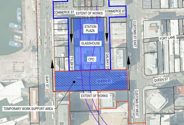
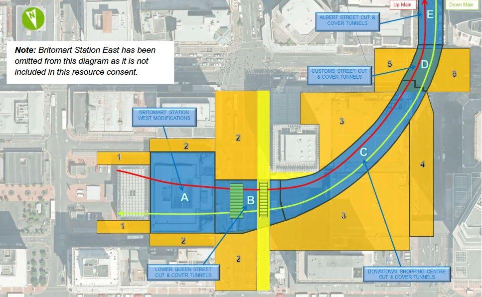
The works (the Project) involve the construction of an extension to the existing passenger rail network from the current termination point within the Britomart Transport Centre (BTC), westwards underneath the former Chief Post Office building (CPO) and Lower Queen Street. The Project footprint is shown by the blue shaded area in Figure 1.1 below.
CRL alignment
BTC designation
CRL designation
C1 worksite
This ITA EMP has been prepared to manage adverse effects relating to industrial and trade activities required during construction of the Project, including a bentonite treatment plant, jet grout plant and the storage and handling of hazardous substances. Specifically, the purpose of the plan is to identify those activities to be undertaken at the Project site that may result in contamination of land and/or stormwater, and to document the procedures to be implemented to appropriately manage these risks.
The ITA EMP is required under Condition 96 of Discharge Permit R/REG/2014/5436 for the CRL Britomart to Wyndham Street enabling works. The plan is an updated version of the Draft ITA EMP – Britomart to Wyndham, dated December 2014, prepared by Golder Associates (NZ) and submitted to Auckland Council (AC) as part of the regional resource consent applications for the Project.
The ITA EMP outlines the following:
• Identification of industrial and trade activities to be undertaken during the Project that may result in contamination of land and/or water;
• Identification of potential contaminants associated with these activities;
• The methods to be used to prevent identified contaminants from contacting stormwater runoff and methods to manage environmental risks from on-site activities;
• An appropriate monitoring and auditing programme to ensure site performance is undertaken in accordance with this ITA EMP; and
• Staff training.
This ITA EMP has been prepared by Tonkin & Taylor Ltd (T+T) for the Downer Soletanche Bachy Joint Venture (the Contractor – DSBJV) and forms part of the Construction Environmental Management Plan (CEMP) for the Project.
Table 1 1 below identifies the relevant conditions of Discharge Permit R/REG/2014/5436 and where these are addressed in the ITA EMP
Table 1.1: Industrial and Trade Activity conditions and location in the document
Condition No. Condition
Site Management
96 At least 20 working days prior to the commencement of construction, a final Industrial and Trade Activities Environmental Management Plan (“EMP”) shall be submitted to the Council (Team Leader Central Monitoring) for certification. The Consent Holder shall request the Council’s (Team Leader Central Monitoring) determination as to whether the EMP can be certified, in writing, within 10 working days following receipt of the EMP. The EMP shall be prepared by a senior qualified person and shall include, but not be limited to, the following:
96 (a) Identification of the specific activities conducted on the site;
This document
Section 1.3
Sections 2 and 3
96 (b) Identification of potential contaminants associated with these activities; Section 3
96 (c) Methods used to prevent identified contaminants contacting stormwater runoff as far as practicable and methods to manage environmental risks from site activities;
96 (d) An Emergency Spill Response Plan (which includes the provision that all spills over 20 litres, or any spill of Environmentally Hazardous Substances that has entered the stormwater system, a water-body or has contacted unsealed ground, shall be reported immediately to the Auckland Council’s 24 Hour Pollution Hotline (09-377-3107);
96 (e) An up-to-date and accurate site drainage plan showing the location of all site catchpits and the final discharge point(s) of the site stormwater system;
96 (f) An appropriate auditing programme to ensure site performance with all components of the sites EMP;
96 (g) Methods for providing and recording staff training; and
96 (h) A monitoring programme as outlined in Condition 101.
97 The Consent Holder shall ensure that the site is operated and managed in accordance with the certified EMP to ensure the risks from the site are managed appropriately
Sections 4.14.6.
Section 5 and Appendix B.
Section 3.2 and Appendix E
Section 7.2
Section 8.3
Section 6.1
This document
98 The Consent Holder shall ensure that a copy of the certified EMP is kept on site and accessible at all times. This document
Structural Controls
99
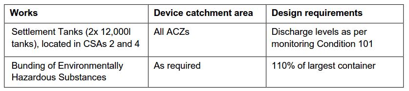
The Consent Holder shall ensure that the following structural controls are constructed for the following catchment areas and design requirements and they are completed prior to discharges commencing from the site.
100 In the event that any minor modifications to the structural controls system are required, the following information shall be provided to Council:
a. Plans and drawings outlining the details of the modifications; and
b. Supporting information that details how the proposal does not affect the capacity or performance of stormwater management system.
All information shall be submitted to, and the proposed modifications certified by the Council (Team Leader Central Monitoring), prior to implementation.
101 Within 30 days of the installation of the water treatment system, and prior to operation, a discharge monitoring programme, to assess the ongoing adequacy of all management practices, shall be developed and submitted to the Council (Team Leader Central Monitoring) for certification. The monitoring programme shall include, but not be limited to:
a. sampling location for final discharge from the site(s);
b. sampling locations on site (i.e. swale inlets, outlets etc);
c. methods and procedures for discharge sampling on a quarterly basis;
d. monitoring parameters for analysis, which shall include: Daily
• Turbidity (NTU)
• pH Weekly
• Total Suspended Solids mg/L
• Copper (total) mg/L
• Zinc (total) mg/L
• Lead (total) mg/L
• Total Petroleum Hydrocarbons mg/L
e. identified trigger levels for each of the above parameters. These trigger levels shall be developed with reference to the ANZECC Guidelines for water quality where applicable; and
f. the methods and procedures for investigating and reporting stormwater discharge monitoring results to the Council (Team Leader Central Monitoring).
102 The discharge monitoring programme shall be implemented upon completion of works required by Condition 99.
Section 2.5 and Project Erosion and Sediment Control Plan (ESCP) 1
ESCP Section 4.13 and Appendix B (CTMP)
Section 6.1
Section 6.1
Reporting
1 Settlement tanks are located in CSA A (adjacent to Galway Street) as opposed to CSA B / CSA 2 (Lower Queen Street) in order to create a more efficient CSA layout
103
104
Within five working days of sample results showing contaminants exceeding the agreed trigger levels (Condition 101(e)):
a. an investigation shall be undertaken to determine why exceedances were detected and to identify any additional source controls or treatment required; and
b. the results of the investigation shall be reported to the Council (Team Leader Central Monitoring).
Within eight weeks following the start of the monitoring required by Conditions 101 and 102, a monitoring report shall be submitted to the Council (Team Leader Central Monitoring). The monitoring report shall include, but not be limited to, the following:
a. a summary of the monitoring results to date;
b. an interpretation of those results and suggestions for improvement to the site operations;
c. a programme for ongoing monitoring including the reporting of results; and
d. a programme for the ongoing maintenance of the discharge water management and treatment system.
This ITA EMP has been prepared by Rob Van de Munckhof. Rob holds a chemical engineering degree and has over 14 years’ experience in environmental management and has experience in Industrial and Trade Activity assessment and management. He has undertaken assessments of surface water discharges from a range of industrial sites and is experienced in undertaking risk assessments to identify priority contaminants. He is experienced in the development of environmental management plans and surface water monitoring plans.
AT is seeking an Infrastructure Sustainability Council of Australia (ISCA) Infrastructure Sustainability (IS) Rating. Further details can be found in the Project CEMP and Sustainability Rating Management Plan. Project sustainability requirements that relate directly to this ITA EMP are included in Appendix A. These requirements are imbedded within the plans to ensure that sustainability is a key focus and ‘the way we do things’.
In some cases the IS requirements and sustainability goals enhance the designation requirements.
This ITA EMP is a living document that will be reviewed and updated if needed during the course of the Project to reflect any material changes associated with construction techniques or the natural environment. Any proposed changes to the ITA EMP must be certified by AC prior to any on-site activity reliant upon the change commencing. A formal review process is described in Section 9 of this ITA EMP.
The Project involves the construction of an extension to the existing passenger rail network from the current termination point within the BTC, westwards underneath the CPO and Lower Queen Street. Separate works are being undertaken to continue the CRL tunnels from this point under the Downtown Shopping Centre site (which is to be redeveloped by Precinct Properties), and then up Albert Street.
Significant works beneath the CPO will be undertaken, with the construction of two new rail tunnels extending westwards beneath the basement floor level. In Lower Queen Street, secant piling will be extended across the road corridor, excavation undertaken to form the rail tunnels followed by reinstatement of the road corridor following the completion of works. During construction, existing ticketing and retail functions and pedestrian access to the station will be accommodated in Station Plaza, at the rear of the CPO building.
Surface works will also be required in QEII Square associated with the Downtown Shopping Centre redevelopment, including construction of the CRL rail tunnels beneath this site (Precinct Properties scope of work).
A detailed description of the construction works is provided in the CEMP.
2.2
The Project will be divided into four discrete active construction zones (ACZ) as shown in Figure 2.1.
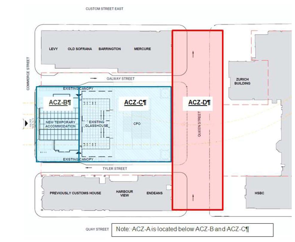
The referencing of Project ACZs adopted in this ITA EMP reflects that of the BTC designation in order to ensure consistency across all Project Delivery Work Plans (DWP) and Environmental Management Plans. It
is noted that under the resource consents, the Project area is separated into two larger ACZ’s – ACZ A (CPO) and ACZ B (Lower Queen Street) – refer to Figure 2 3
A summary of the key construction activities that will be undertaken in each ACZ is outlined in Table 2 1 A detailed description of the construction works is provided in the CEMP.
Table 2.1: Summary of key construction activities within each ACZ 2
ACZ
Key construction activities
A Britomart Station modifications
• Modification of existing platforms and track lines
• Installation of temporary access stairs, station entry and egress
B Accommodation within Station Plaza
• Construction of temporary accommodation buildings and facilities and relocation of ticketing, staff facilities, public amenities, retail/kiosk areas from the CPO building
• Installation of services.
C CPO Building Works
• Removal of the CPO fixtures and fittings
• Saw cutting and demolition of the CPO ground floor
• Installation of guide walls, diaphragm walls and underpinning structures to provide support for the CPO
• Soil excavation
• Construction of the base slab, walls and roof for the new rail tunnels
• Backfill excavation
• Reinstatement and fit out of CPO building
D Lower Queen Street
• Bentonite plant located adjacent to the south west corner of the CPO building on Lower Queen Street
• Carry out piling and underpinning works
• Soil excavation
• Construct base slab, walls and roofs for new rail tunnels
• Backfill excavation
• Reinstatement of Lower Queen Street
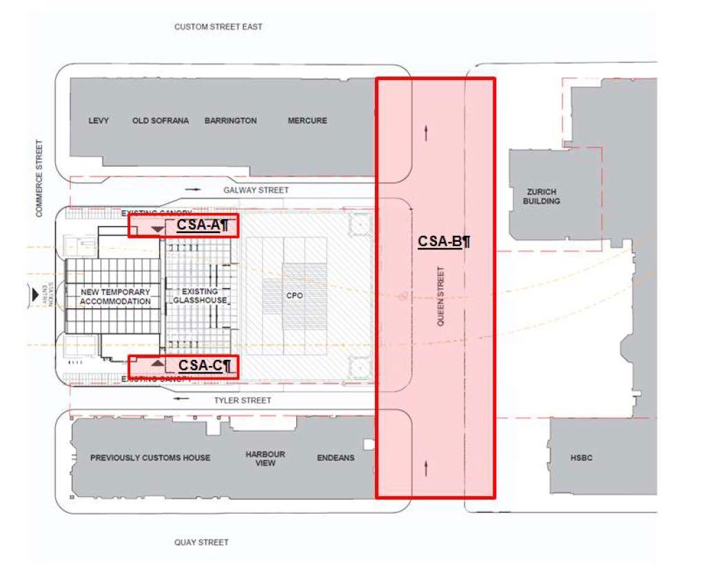
Three construction support areas (CSA) are proposed to support the ACZs (refer to Table 2.2 and Figure 2.2 of this ITA EMP.
Table 2.2: Construction Support Areas CSA
A Galway Street Supports temporary accommodation works in Station Square 400 m2
2 Note these activities are not in order of programme
• Material storage
• Crane location and access to CSA A
• Stormwater and groundwater treatment tanks
B Lower Queen Street Supports CPO and Lower Queen Street construction
C Tyler Street Provides construction access to the CPO
3,500 m2
• Bentonite treatment plant
• Jet grout pump and mixing plant
• Material storage
400 m2
• Temporary site office during Stage 1 of the Project
• Material storage
• Crane location and access to CSA C
• Main vehicle entrance to the CPO building
2 2: Construction Support Areas 3
The referencing of Project CSAs adopted in this ITA EMP reflects that of the BTC designation to ensure consistency across all Project DWPs and Environmental Management Plans. It is noted that under the resource consents, the Project area is separated into two CSAs – CSA 1 and CSA 2 – refer to Figure 2.3.
3 Note: Blue hatched areas on Figure 2.2 show the areas of the Lower Queen Street that will be maintained as traffic lanes in order to provide vehicle access from Lower Queen Street to Tyler Street and Galway Street into Lower Queen Street
The diaphragm wall and jet grout columns will require the establishment of bentonite and jet grouting plants on Lower Queen Street adjacent to the CPO building, the location of which are shown on Figure 2 4 The operation of the plants is outlined in Sections 2.4.1 and 2.4.2 below.
A bentonite plant will be located adjacent to the south west corner of the CPO building on Lower Queen Street. The purpose of the plant is to mix and recycle bentonite slurry associated with the diaphragm wall construction.
The plant will cover an area of approximately 250 m2 and comprise the following elements:
• Six silos, approximately 12 m in height, required for the storage of bentonite slurry, water and waste;
• Slurry Treatment Plant (STP) / De-sanding Unit - composed of 12 20” container with a capacity of approximately 500 m3;
• Bentonite mixer;
• Bentonite storage bags;
• Generator; and
• Excavator.
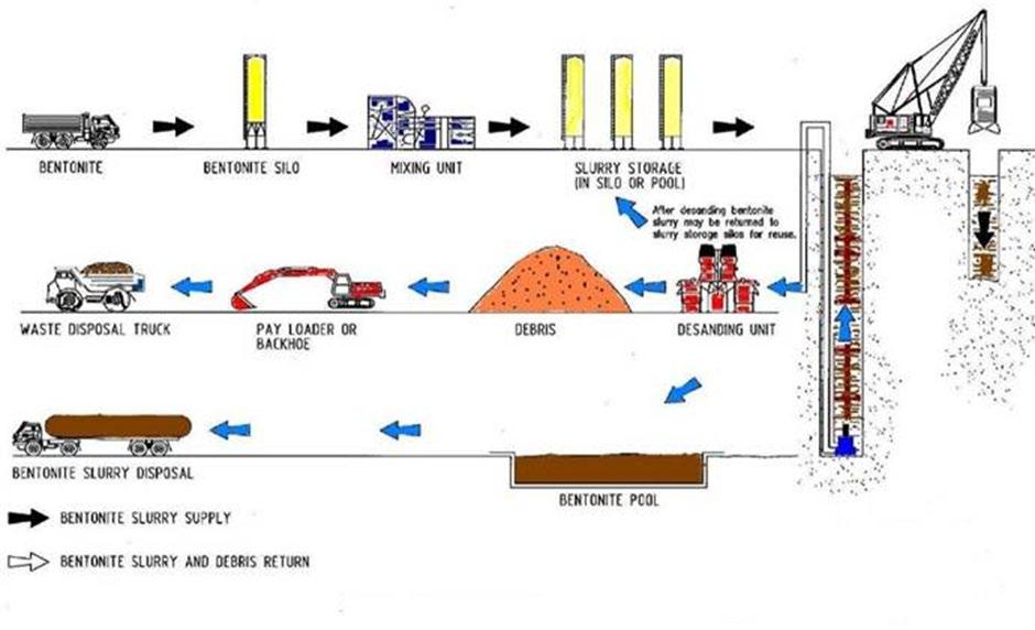
The bentonite plant operation is outlined in Table 2.3 and shown on Figure 2.5.
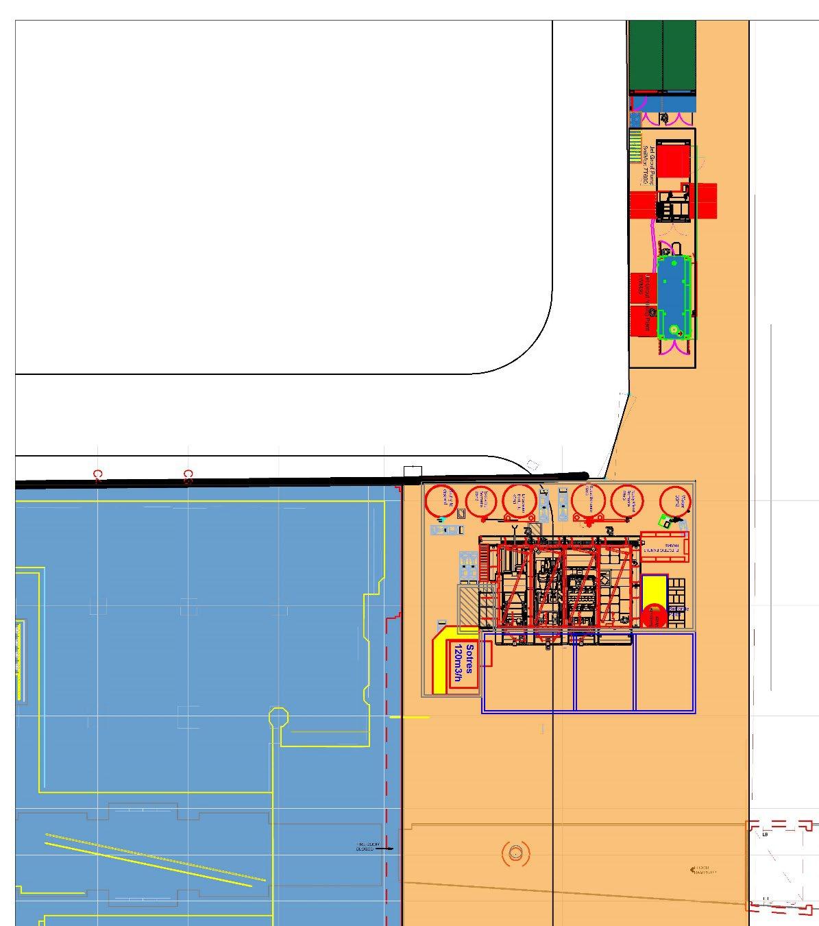


Table 2.3:
Bentonite Storage
Bentonite Mixing and Recycling
Spoil Disposal
Plant Operation
• Storage of bentonite powder and slurry within silos
• Mixing of bentonite with water and additives (sodium bicarbonate, carbonate and bentocryl) to make a bentonite slurry, which will be temporarily stored within the silos before being used in the piling operations. The bentonite mixer will be covered to control bentonite powder dust emissions.
• Transfer of the bentonite slurry to the storage silo, which is connected to the circuit of the STP / de-sanding unit and down to the diaphragm wall operations via pipes and hoses.
• Slurry will be pumped out from the trench and travel back to the de-sanding unit / STP, where it will be treated to remove solids and recover the slurry for re-use.
• Dry material recovered from the de-sanding unit will be removed off-site.
• Liquid spent slurry following de-sanding will be discharged into a temporary spoil pit (approximately 65 m3) to be located on site. The spoil will be excavated and transported via trucks (approximately 1-2 per day) to an approved disposal facility.
• The entire bentonite plant will be bunded to contain any spilt material or bentonite slurry in the event of a pipe or pump failure during transfer of the slurry.
• Any surface water collected in the bunded area will be pumped to the water treatment plant in CSA A for on-site treatment prior to discharge. There will be no gravity discharge of any water from the bunded area to the stormwater system. Prior to commissioning of the water treatment plant, all water will be disposed of offsite by a licenced liquid waste contractor.
• Any spilt material pumped to the sediment control system will be treated as per other sediment laden water on -site with discharge only occurring once the minimum water quality standards are met.

The main function of the jet grout plant is to mix the cement grout required for the jet grout columns and transfer it to the jet grouting rig at high pressure. The plant will be located to the south of the Bentonite Plant on Lower Queen Street (refer Figure 2.3)
The plant will comprise the following elements:
• Batching plant;
• High pressure pump; and
• Horizontal silo for cement powder storage
The jet grout mixing plant will involve mixing water and cement and additional additives to create a slurry mix as outlined in Table 2.4.
Material Storage
Cement Grout Mixing
Cement grout injection:
Spoil Disposal
Management of Discharges
• Cement powder will be delivered to the plant by trucks. It will be pumped to the storage silo through hoses. Dust filters on the silos will be used to control dust emissions.
• Cement powder will travel to the mixer via a closed screw conveyor. The scale will have a protective cover to control dust.
• Cement powder will be mixed intermittently with water in the required proportions and the grout will then be stored in a tank.
• Grout will travel via hoses, filters and pumps to the high pressure pump, then to the jet grouting rig and through the drill string, which will inject this grout at high pressure, inside the soils, to form jet grouting columns.
• The resulting sludge “spoil” (made of grout, water and soil) will be pumped from the jet grout column location to the spoil pit at the plant.
• It will be disposed of in a similar manner to the slurry spoil.
• The jet grout plant will be bunded
• Any surface water collected in the bunded area will be pumped to the water treatment plant on-site for treatment prior to discharge. There will be no gravity discharge of any water from the bunded area to the stormwater system. Prior to commissioning of the water treatment plant, all water will be disposed of offsite by a licenced liquid waste contractor.
• Any spilt material pumped to the sediment control system will be treated as per other sediment laden water on -site with discharge only occurring once the minimum water quality standards are met.
Stormwater and groundwater that settles in the excavation in Lower Queen Street and the CPO will be pumped via a collection tank (either 10 m3 LQS tank, or 3 m3 CPO tank), to the WTP collection tank (8 m3), where sediment will settle out. Assisted sediment settlement using chemical or non-chemical flocculants (the latter being preferred if effective) will be undertaken as required to ensure water discharged from the system will not result in adverse effects on the receiving environment. The treatment tanks will be located adjacent to the south east corner of the CPO adjacent to the glasshouse.
The treatment plant is outlined in detail in Section 2 of the Chemical Treatment Management Plan (CTMP) for the Project (Appendix B of the Project ESCP).
The main industrial and trade related activities to be undertaken in each ACZ are outlined in Table 3.1. This table also outlines the potential contaminants associated with the activities and the relevant procedural and physical controls to be implemented during the works to minimise any adverse environmental effects.
Links to several related plans/registers are provided in Table 3.1. The Project WARRMP is relevant to the management of material that needs to be disposed of from the Project area. Refer to Section 4.4 of this ITA EMP for further detail on this plan.
Table 3.1: Summary of activities, potential contaminants and controls
Active Zone Activity
ACZ-D Bentonite treatment plant
Bentonite storage
Mixing unit
Slurry storage
De-sanding unit
Spent bentonite tank
Dry debris
ACZ-D Jet Grout Plant
Contaminants
Sediment
Sediment, pH 4
All zones Chemical store Hydrocarbons, oils and greases, fuels
ACZ-D Concrete
Sediment, pH
Procedural controls
• Bentonite Plant Spill Response Plan.
• WARRMP
Physical controls
• Bentonite plant shall be bunded with runoff directed to the on-site water treatment plant
All zones General site activities
Vehicle refuelling
Hydrocarbons, fuels
• Jet Grout Plant Spill Response Plan.
• WARRMP
• Risk Register
• Risk Register
• ESRP
• WARRMP
• Jet grout plant area shall be bunded and drain to the on-site water treatment plant.
• All chemicals shall be stored within a bunded enclosure.
• No washing out of concrete trucks shall be undertaken on-site
• All runoff from high risk areas of the site shall be directed to the water treatment plant with pH monitoring undertaken
• Risk Register
• ESRP
• Drip trays must be in place during refuelling
4 Cement and other additives that will be used in the Jet Grout Plan and Concreting activities during the Projects can increase or decrease pH outside normal ranges
Equipment washdown
Sediment, hydrocarbons, oil & grease, heavy metals
Waste handling and storage
Sediment, hydrocarbons, oil & grease, heavy metals
• Risk Register
• WARRMP
• ESRP
• Risk Register
• Spill kit to be available in close proximity to activity
• Washing of equipment shall only be undertaken within the excavation area/designated area draining to the treatment plant.
• No vehicle washing shall otherwise be undertaken on-site.
• All waste bins shall be stored in a covered area on-site, or have lids.
All existing stormwater drains within the site area have been removed/sealed.
Stormwater from within the bunded truck load out area to the north of the excavation, as well as the wheel wash and surrounding hardstand area to the south of the excavation, drain to the onsite water treatment plant. The remaining stormwater from the site drains via overland flow into the public stormwater system around the site.
The public stormwater network discharges directly into the Waitemata Harbour at one of three two discharge locations in the Port – Central Wharf/Captain Cook Wharf (CSA A & C) and Queen’s Wharf (CSA B) Refer to Section 4.6.3 of the ‘Auckland City Rail Link Britomart to Wyndham Water Quality Assessment’ dated December and prepared by Golder Associates for information on the receiving environment water quality.
The release of contaminants to the stormwater network will be managed using the controls described in the Project ESCP and this ITA EMP. Site layout plans have been prepared (refer to Appendix E of this ITA EMP) to show the location of the bentonite plant, the jet grout plant, truck routes and any chemical storage areas.
Final as-built drainage plans for the Project area will be prepared following the completion of the works. These plans will show the locations of all stormwater catchpits and discharge locations within the Project area
The main environmental risk associated with the bentonite plant is the discharge of sediment laden water to stormwater drains within the Project area, which in turn discharge into the Waitemata Harbour.
To avoid or minimise any discharges from the bentonite plant to the surrounding environment, the plant will be designed and operated as follows:
• The entire bentonite plant shall be bunded to contain any spilt material or bentonite slurry in the event of a pipe or pump failure during transfer of the slurry.
• The outlet of the existing stormwater catchpit in Lower Queen Street that will be located within the bentonite plant operation area (refer to the Stormwater Drainage Plan in Appendix E of this ITA EMP) will be sealed off during the works, and a submersible pump installed to pump any surface water that collects in the bund to the bentonite plant tanks for re-use; or to the water treatment plant.
• Sodium bicarbonate and bentocyrl will be added to the bentonite slurry. Neither chemicals are classified under HSNO as hazardous, and will be stored within the bunded bentonite plant area. No other environmentally hazardous substances will be required as part of the bentonite plant operation.
• In the event of a spill outside of the bunded area, the standard spill control procedures will be implemented to contain and manage the spill (refer to Section 5 of this ITA EMP).
• Prior to commissioning of the bentonite plant, a Spill Response Plan was prepared for the plant (refer Appendix C). This Plan outlines the environmental controls and spill response procedures specific to the operation of the plant detailed in Section 2.4.1 of this ITA EMP.
The extent of the bunded area and the location of the existing catchpit within the operational area of the bentonite plan that will be sealed off during the works is shown on the Stormwater Drainage Plan in Appendix E
The main environmental risk associated with operation of the jet grout plant is the discharge of sediment laden water and elevated pH from cement used in the slurry mix.
To avoid or minimise any discharges from the jet grout plant into the surrounding environment, the plant will be designed and operated as follows:
• The jet grout plant shall be bunded with any surface water collected in the bund draining to the onsite water treatment plant. The outlet of the existing catchpit in the plant operation area (refer to the Stormwater Drainage Plan in Appendix E) will be sealed off, and a submersible pump installed to pump surface water to the sediment treatment plant.
• In the event of a spill outside of the bunded area, the standard spill control procedures will be implemented to contain and manage the spill (refer to Section 5 of this ITA EMP).
• Prior to commissioning of the jet grout plant, a Spill Response Plan will be prepared for the Plant (Appendix D). The Plan will include the relevant environmental controls and spill response procedures specific to the operation of the plant detailed in Section 2.4.2 of this ITA EMP.
The principal environmentally hazardous substances that will be stored and used during the construction works will include:
• Fuel (e.g., petrol, diesel); and
• Oils
Dangerous and hazardous substances shall be stored on site in accordance with the Health and Safety at Work (Hazardous Substances) Regulations 2017 and relevant HSNO regulations, and subject to provisions relating to Location Test Certificates and Approved Handlers, as appropriate.
All chemicals are stored in a secure area with secondary containment to contain any spills. The main storage area is in the DG shipping container located adjacent to the northern site boundary in Lower Queen Street, with supplementary storage area close to the southern site boundary in Lower Queen Street (bunded platform). There is some local storage of chemicals inside the CPO (e.g., hydraulic oil). For all local storage, chemicals must be stored on spill pallets to provide appropriate secondary containment.
Safety Data Sheets (SDS) for all of the chemicals used or stored in the Project area will be kept in the Project site office with a sub-set on file at each storage location relevant to the specific materials being stored A Hazardous Substances and SDS register shall be kept on-site and regularly maintained to ensure it is up to date with the chemicals and volumes of chemicals used and stored on-site.
Spill kits and associated spill response equipment, will be available at a minimum in each CSA (e.g., one CSA A & C in Tyler and Galway Streets, and one in CSA B in Lower Queen Street, refer to Appendix E of this ITA EMP) In addition, two spill kits will be available at all times at the Bentonite Plant and Jet Grout Plant, and a further six spill kits will be available inside the CPO Building close to the D wall equipment.
For the purpose of the Project, waste material refers to items removed from worksites and road carriageways, such as surplus or reject spoil, excavated seal, pipes, rubbish detritus and any other unwanted materials. Appropriate disposal shall be arranged for any material that requires off-site disposal.
If hazardous material requires off-site disposal, it will be disposed of safely, through an appropriate contractor authorised to handle, transport, process or safely dispose of the waste concerned to an approved disposal facility.
Any waste bins on-site will either be stored undercover, or will be installed with covers to prevent rainwater ingress. The only exception to this is the site waste skip, which it is not practicable to cover.
Overall waste management or disposal requirements will vary depending on the material concerned and shall be undertaken in accordance with the WARRMP.
No permanent storage of bulk fuels will occur on-site. Refuelling of plant and equipment will be undertaken using either a mini-tanker for larger equipment, or portable containers (such as jerry cans) for smaller plant and equipment.
For works involving refuelling, refer to key controls outlined in environmental risk register.
No vehicle wash-down will be undertaken on-site, apart from localised washing of vehicles and tyres as required in order to prevent the tracking of sediment onto the surrounding road network. The location and nature of the construction works, along with the construction methodology will serve to minimise the potential for site vehicles to drive over areas of open excavation or unpaved areas and track dirt onto the surrounding road network.
The removal of spoil from the excavations will be undertaken as follows:
• Material will be excavated using diggers within the excavation area or a long reach digger on the edge of the excavation;
• Trucks will back up to the edge of the excavation area on the existing sealed surfaces; and
• Material will be loaded directly into the trucks to avoid the storage of excavated material on-site.
In the event of material being spilled onto the ground around the excavation or from trucks transporting the spoil from the excavation, the material will be cleaned up prior to the vehicle leaving the site. This may involve some localised washing of vehicles and tyres. Any runoff from the wash down area will directed to the water treatment plant
Some washing of machinery within the excavation area may be required. In this instance, washing of machinery will be undertaken using a hose or water blaster on-site within the excavation area only.
The management of spills at the site will differ depending on the quantity, type of material and location of the spill.
As no significant volumes of environmentally hazardous substances apart from those at the bentonite and jet grouting plants are anticipated, the spill response procedures for the Project have been divided into three separate procedures as follows:
• General Emergency Spill Response Plan (ESRP), which covers all areas of the site;
• Bentonite Plant spill response plan; and
• Jet Grout Plant spill response plan
A general ESRP has been prepared for the Project (refer to Appendix B of this ITA EMP). The ESRP includes provision that in the event of all spills over 20 litres, or any spill of Environmentally Hazardous Substances, which has entered the stormwater system, a water-body or has contacted unsealed ground, the spill shall be reported immediately to the AC 24 Hour Pollution Hotline (09-377-3107). Additionally, Cooper and Company will be notified if spills (as described above) occur within / or are likely to affect the Britomart Precinct.
The spill response procedures for the bentonite plant is detailed in the Bentonite Plant Spill Response Plan (Appendix C) The spill response procedure for the jet grout plant will be detailed in the Jet Grout Plant Spill Response Plan which will be developed prior to commissioning of the plant (Appendix D)
A site plan has also be developed, which shows the location of all spill kits in the Project area (refer to Appendix E of this ITA EMP) As described in Section 4.3, spill kits and associated spill response equipment/procedures will be available at a minimum in each CSA In addition, two spill kits will be available at all times at the Bentonite Plant and the Jet Grout Plant (one general purpose, one oil only), and a further six spill kits will be available inside the CPO Building close to the D wall equipment (oil only).
Each spill kit will have a register of contents and an inspection sheet. Each spill kit will be inspected monthly to ensure all contents are present and there is no rubbish in the kits. The inspection sheet shall be signed during each inspection.
As required by Condition 101 of Permit REG/2015/4436, a discharge monitoring programme was developed within 30 days of installation of the water treatment system on site and prior to operation. This programme has been certified by AC.
The details of this monitoring programme are provided in Appendix F
6.2
Reporting of the monitoring results shall be undertaken in accordance with Conditions 103 and 104 of Discharge Permit R/REG/2014/5436 as outlined in Table 6.1.
Table 6.1: Monitoring reporting
Condition No. Condition
103 Within five working days of receipt of sample results showing contaminants exceeding the agreed trigger levels (Condition 101(e)):
a. an investigation shall be undertaken to determine why exceedances were detected and to identify any additional source controls or treatment required; and
b. the results of the investigation shall be reported to the Council (Team Leader Central Monitoring).
104 Within eight weeks following the start of the monitoring required by Conditions 101 and 102, a monitoring report shall be submitted to the Council (Team Leader Central Monitoring). The monitoring report shall include, but not be limited to, the following:
a. a summary of the monitoring results to date;
b. an interpretation of those results and suggestions for improvement to the site operations;
c. a programme for ongoing monitoring including the reporting of results; and
d. a programme for the ongoing maintenance of the discharge water management and treatment system.
Regular inspections of the Project area will be undertaken throughout the construction duration as outlined in Section 6 of the CEMP. Site inspections will include inspections of industrial and trade related activities to ensure the integrity of activities and devices is maintained and to minimise the potential for the discharge of contaminants from the Project area that might have adverse effects on the receiving environment. Site inspections will include the following elements:
• Check the appropriate storage of materials on-site in order to prevent spillage;
• Check bunding and containment systems around hazardous substances are intact;
• Check water treatment systems are operating correctly to manage contaminated water;
• Check all loading and unloading areas are clear of spillage and debris;
• Check site for evidence of spills that require clean up;
• Check construction vehicles for signs of leakage;
• Check spill kits are fully stocked, clearly labelled and appropriately located; and
• Check waste bins and containers for capacity, signs of leakage and ensure they are covered to prevent rain water ingress.
An internal environmental audit will be undertaken on a quarterly basis The purpose of the audit is to check the implementation of, and compliance with, environmental management procedures and controls, including those outlined in this ITA EMP. The audit findings will be reported to the DSBJV management team, and will identify any areas of non-conformance, and/or opportunities for improvement.
External environmental and sustainability audits will be completed as per the Project Audit Schedule, and at least annually, to assess the effectiveness of the Environmental and Sustainability Management Systems.
Refer to Section 7.2 of the CEMP for further detail on these audits.
Corrective action is required on the basis of the occurrence of substandard performance being observed or experienced, resulting in an environmental complaint, incident or emergency or where a significant environmental incident or emergency could have occurred. Refer to Section 6.2 of the CEMP for further detail on corrective and preventative action during the Project.
All Project staff (including subcontractors) will undergo general environmental awareness training, along with training in relation to the risks associated with industrial and trade activities outlined in this ITA EMP and to ensure that the appropriate control measures are properly implemented.
Suitable induction and ongoing environmental training will be established and maintained to ensure employees and subcontractors are aware of:
• The importance of conformance with the Environmental Policy, the requirements of the project CEMP and company procedure;
• The significant environmental aspects, actual or potential, of activities and the environmental benefits of improved performance;
• Their roles and responsibilities in achieving conformance with the environmental policy, company procedures and this ITA EMP;
• The potential consequences of departure from specified operating procedures;
• Spill response and emergency procedures; and
• Accident and incident reporting and methods of prevention.
Refer to Section 4.2.1 of the Project CEMP for further detail on employee training.
The HSNO Act 1996 requires that certain hazardous substances are under the control of an Approved Handler. Any staff required to handle such substances will be required to hold or obtain an Approved Handler Certificate.
Visitors to the site are required to attend a DSBJV site induction. This induction will cover the key environmental risks onsite, including those associated with industrial and trade activities outlined in this ITA EMP where relevant. A shortened visitor induction may be used when the visitor only requires access to the site for the day, and will be accompanied by a DSBJV team member at all times (refer to Section 4.2.2.2 of the Project CEMP)
Staff training will be recorded as outlined in Section 4.2.7 of the Project CEMP.
This ITA EMP will be reviewed throughout the course of the Project:
a To reflect material changes associated with changes to construction techniques, the natural environment or due to unresolved complaints.
b As part of the annual management review of the ITA EMP.
A management review of the ITA EMP will be undertaken at least annually by the Project Management Team and AT representatives. The management review will be organised by the Project Environmental and Sustainability Manager and the Project team will be informed of any changes to this ITA EMP through the regular Project communications processes. The review will take into consideration:
• Compliance with the designation or consent conditions, the CEMP, DWPs and EMPs (including site specific plans) and material changes to these plans.
• Any significant changes to construction activities or methods.
• Key changes to roles and responsibilities within the Project team
• Changes in industry best practice standards.
• Changes in legal or other requirements (social and environmental legal requirements, consent conditions, AT objectives and relevant policies, plans, standards, specifications and guidelines)
• Results of inspections, monitoring and reporting procedures associated with the management of adverse effects during construction.
• Comments or recommendations from AC regarding the CEMP, DWPs and EMPs.
• Unresolved complaints and any response to complaints and remedial action taken to address the complaint.
Attached as Appendix G is an explanation of how any CLG comments received to date are addressed in the ITA EMP.
The process for updating this ITA EMP as a result of a material change to the Project or the annual review, is as follows (refer to CRL designation Condition 23 for further information):
• Any material change to this EMP must be consistent with the purpose and objective of the relevant conditions listed in Table 1.1 of this document.
• Affected parties and the CLG must be notified of the review and any material change proposed to this EMP.
• This EMP must clearly document the comments and inputs received from affected parties in relation to any material changes, along with a clear explanation of where any comments have not been incorporated, and the reasons why not.
• Any material change proposed to this DWP shall be subject to an independent peer review as required by CRL Condition 11.
Any material change proposed to this DWP relating to an adverse effect shall be submitted for approval to Auckland Council Compliance and Monitoring Officer, at least 10 working days prior to the proposed changes taking effect. If any changes are not agreed, the relevant provisions of the RMA relating to approval of outline plans shall apply.
A copy of the original ITA EMP document and subsequent versions will be kept for the Project records, and marked as obsolete. Each new / updated version of the ITA EMP documentation will be issued with a version number and date to eliminate obsolete ITA EMP documentation being used.
A summary of the review process will be provided annually to Auckland Council and otherwise be made available on request.
All project documentation is created, reviewed, approved, issued, revised, retained, and superseded in accordance with the project’s Document Management & Control Plan, which includes the requirement for records of review and authorisation to be maintained.
The following project-specific documents need to be created to support the processes described in this plan:
1. Environmental and Sustainability Risk Register
1.1. Annual Risk Assessment Review Minutes
1.2. Records of Register Review
2. Spill Response
2.1. General Emergency Spill Response Plan
2.2. Bentonite Plant Spill Response Plan
2.3. Jet Grout Plant Spill Response Plan
3. Site Drainage and Layout Plan
4. HSNO
4.1. Location Test Certificates
4.2. Approved Handler Certificates
4.3. MSDS Register
4.4. MSDS Short Reference List
4.5. Records of MSDS review
5. Spill kits
5.1. Register of Contents
5.2. Inspection Form
5.3. Monthly Inspection Records
6. Discharge Monitoring Programme
6.1. Daily Inspection Form
6.2. Daily Inspection Records
7. Site Inspection Records
7.1. Weekly E&S site inspection forms
7.2. Monthly E&S site inspection forms
7.3. Corrective action tracking register
8. Project Induction
8.1. Full Induction Presentation Content
8.2. Full Induction Register
8.3. Visitor Induction
9. Training
9.1. Training register
Review
10.1. Annual ITA EMP review record
Table A identifies the ISCA Credit Requirements relevant to this ITA EMP and where they are addressed in the documents.
Table A: ISCA Requirements
Credit Requirement *
DIS-1
Level 1
DIS-1
Baseline studies of existing receiving water environment have been carried out for the Project
Level 1 Predictions for receiving water quality impacts have been developed for construction
DIS-1
Level 1
DIS-1
Measures to minimise adverse impacts to local receiving water quality identified and implemented
Level 1 Monitoring of water discharges and receiving waters is undertaken at appropriate intervals and at times of discharge during construction
DIS-1
Level 2
DIS-1
Modelling demonstrates no exceedances of water quality goals
Level 2 All stormwater leaving the site is treated or filtered in accordance with appropriate urban stormwater guidelines unless it occurs during a 6 hour 1 in 5 year storm event
Relevant section
Section 3.2
Section 3
Sections 1.1, 2.5, 3, 4.1, 4.2, 4.3, 4.4, 4.5, 4.6, 5, 7.1
Section 6
Comments
Refer also to the Water Quality Assessment Report by Golder Associates, dated Dec 2014 and the CTMP
Refer also to the Water Quality Assessment Report by Golder Associates, dated Dec 2014 and the CTMP
Refer also to the CTMP and Contaminated Soils Management Plan
Refer also to the CTMP
Section 6
* Refer to ISCA Rating Tool for full details of the requirement
Refer also to Monitoring Results and Reports
Refer to the ESCP and the CTMP
Comments received from the CLG are as follows:
4 May 2016 Cooper and Company Section 9, ITA EMP Review, sets out the formal review process and mentions taking into account comments or recommendations of Council but doesn’t mention the CLG. Condition 19 states that the consent holder is required to consult with the CLG upon the review of this plan. Reference should be included here of this obligation.
4 May 2016 Cooper and Company Appendix B, Work Instructions –W 102 – Refuelling. The purpose statement is missing a “not” i.e. “To ensure that onsite machinery, equipment and storage tanks do not cause pollution to the environment”.
4 May 2016 Cooper and Company Appendix C – Spill Response Plan – Emergency Spill and Runoff Response Flow-chart talks about who will be notified and that neighbours will be notified “where applicable”. Cooper and Company would want to be notified of any spills within/affecting the Britomart Precinct.
20 May 2016 Cooper and Company
Section 5 Spill Response has a typo “as described above”.
Section 9 text been updated to reflect Condition 19 requirement to consult with the CLG upon the review of this plan.
Appendix 1 text is in the process of being corrected.
Section 5 and the flow chart in Appendix C has been updated to include notification of Cooper and Company of spills within the Britomart prescient when applicable.
Section 5 text updated to fix typo.
• Annual Review 2017
Updates have been made to the following sections:
• Section 2.1 – change in method from sheet piling to secant piling in LQS.
• Table 2.1 – delete reference to processing concrete onsite for use as backfill as this is no longer proposed
• Section 2.2 – remove reference to roof structure over LQS excavation
• Section 2.4.1 – update to the description of the bentonite plant following construction/commissioning
• Figure 2.4 – update to figure to reflect change in jet grout plant location from NW corner of CPO Building, to area between hoardings in LQS to the south of the Bentonite plant
• Table 2.3 - addition of carbonate as additive to bentonite
• Table 2.3 / 2.4 – change in wording relating to what happens with surface water collected in the bunded area around the bentonite plant and jet grout plant. Removed reference to sediment control system, for sediment removal, and replaced with water treatment plant, for treatment as they system is designed to deal with treatment for parameters other than just sediment.
• Section 2.4.2 – update to the location and description of the jet grout plant following construction/commissioning.
• Section 2.5 – removed reference to treatment plant capacity as this is covered in detail in the ESCP.
• Section 3.0 – Reference to project risk register inserted
• Section 3.0 – Removed reference to Downer work instructions as these have been decommissioned. Instead controls will be captured in the risk register.
• Table 3.1 – removed reference to sediment control system as per Table 2.3/2.4 comment above, and replaced with water treatment plant.
• Table 3.1 – removed all reference to Downer work instructions as per Section 3.0 comment above.
• Table 3.1 – inserted physical controls around refuelling activities.
• Section 3.2 (old) – removed this section, and moved summary text into Section 3.1.
• Section 3.2 (new) – amended discharge location for stormwater from the site.
• Section 4.1 – removed reference to chemicals from bentonite plant being environmental risk, as they are not hazardous substances.
• Section 4.1/4.2 – changed reference from sediment treatment plant, to water treatment plant.
• Section 4.3 – Amended principal environmental hazardous substances based on current site register. Updated text to show where hazardous substances are being stored on the site and the location and number of spill kits onsite. Removed reference to Downer work instructions.
• Section 4.4 – inserted exception to rule of covering bins for site skip which isn’t practicable to cover.
• Section 4.5 – changed reference to controls for refuelling from work instructions to environmental risk register.
• Section 5.0 – updated status of bentonite and jet grout plan spill response plans.
Date
October 2017
• Section 6.1 – updated to reflect that the discharge monitoring programme has been written/certified by council, and providing a link to the document. Removed consent condition requirements of this programme as they are covered in the document.
• Section 7.2 – changed auditing requirement to remove requirement to audit the sustainability management systems on a quarterly basis.
• Section 8.2 – update to induction process.
• Section 10 – new section outlining the project specific documentation required to support the processes described in the ITA EMP.
• Appendix B – deleted
• Appendix C – inserted updated general SRP, now Appendix B
• Appendix D – new Bentonite Plant SRP
• Appendix E – new placeholder for Jet Grout Plant SRP
• Appendix D – site drainage plan, now Appendix E
• Appendix E – new discharge monitoring programme
• Appendix F – CLG comments, now Appendix G
Updates have been made to the following sections:
• Section 2.5 – updated the description of the stormwater/groundwater treatment system
• Section 3.1 – corrected reference to the Waste Avoidance and Resource Recovery Management Plan (WARRMP). Updated description of site drainage/treatment
• Section 3.2 - updated description of the site drainage since works were completed to remove all stormwater drains onsite, and collection/treatment system was installed
October 2018