This document is uncontrolled when printed. This document should be printed in colour
Revision Status
Rev A00 20 April 2020 Draft for Auckland Council and Independent Peer Review
Rev 000 16 June 2020 Final for Pre-lodgement
Rev 001 29 June 2020 Final for submission
Rev 001A 22 July 2020 Final addressing Council comment
Approval Status
Prepared by: Mike McConnell Erosion and Sediment Control Advisor
Approved by: Peter Roan Consenting Lead – Link Alliance
1 Introduction
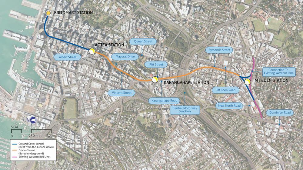
The City Rail Link (CRL) project comprises the construction, operation and maintenance of a 3.4 km underground passenger railway, running between Britomart Station and the North Auckland Rail Line (NAL) in the vicinity of Mt Eden Station. The CRL also involves the construction of two new underground stations at Aotea and Karangahape and a redeveloped Mt Eden Station (refer to Figure 1-1). The design and construction of the CRL infrastructure between the Aotea and Mt Eden Stations is being delivered by the Link Alliance.
This Erosion and Sediment Control Plan (ESCP) has been prepared in relation to the Mt Eden Main Works (“main works”).
1.1 Overview of CRL Works in Mt Eden
CRL works in the Mt Eden area involve the construction of the southern section of the tunnel structures and the tie-in of the CRL railway to the existing NAL, including the construction of the redeveloped Mt Eden Station. The Mt Eden Active Construction Zone (ACZ) and Construction Support Areas (CSAs) are generally located between Nikau Street to the north, State Highway 1 (SH1) to the east, Dominion Road to the west and the existing NAL to the south.
The works in this area include:
• Operational activity required to support the tunnel boring machine (TBM) drive, including control room and plant, storage and spoil handling;
• Construction of a new Mt Eden Station building, incorporating passenger linkages between the new CRL platform and the modified existing NAL platform;
• Road over rail bridges at Mt Eden Road, Normanby Road and Ruru Street with sections of road realignment;
Page 5 | Mount Eden Main Works
Figure 1-1: CRL Route and Location
• Grade separation structures for the existing and new rail lines to pass-over and connect with each other, including the Newton Junction Grade Separation Structure, the Eastern Facing Connection and the Western Facing Connection;
• Construction of a portal vent house building structure;
• Installation of retaining walls and utilities;
• Pedestrian and cyclist bridge structures at Fenton Street and Porters Avenue; and
• New road linkages within the reinstated area post-construction
Given the nature and scale of CRL construction works in Mt Eden, works are being undertaken in a staged manner, involving:
• Enabling and early works (demolition, network utility relocation and site establishment work) – early works have commenced and will continue to end of 2020;
• Main construction works (construction of the underground CRL cut and cover tunnels, grade separation structures and trenches, station building and platforms, and tie-ins to the NAL) to be undertaken from mid-2020 through to mid-2023; and
• Public realm reinstatement – likely to be undertaken from 2021 to early 2024.
1.2 ESCP Staging
To reflect the staged construction approach for the CRL in the Mt Eden area, a series of Stage Specific Erosion and Sediment Control Plans (SSESCP) are being prepared.
This ESCP addresses the main works, which are detailed in the Construction Environmental Management Plan (CEMP) and summarised in Section 2 of this ESCP.
If required, an ESCP will also be prepared for the future public realm reinstatement.
1.3 Purpose of the ESCP
This ESCP has been prepared to identify measures that will be implemented to mitigate and manage the potential adverse effects on the receiving environment from any erosion and sediment generation during the main works
This ESCP addresses the matters specified in Conditions 53-58, 65-72, 139, 141, 144-145 and 167-169 of the regional land use consent R/LUC/2016/1890, and discharge permits R/REG/2016/1895, R/REG/2016/1896 and R/REG/2016/1898 as specified in Table 1-1
Chemical treatment is likely to be required to assist in the settlement of sediments during the construction works. A Flocculant Treatment Management Plan (FTMP) is included in Appendix C of this ESCP, and a brief description is included in section 4.1.2 of this ESCP.
This ESCP forms part of the CEMP for the main works and should be read in conjunction with the CEMP and other relevant Delivery Work Plans (DWP) and Management Plans (MP) for the main works
This ESCP has been prepared in consultation with the CRL Mana Whenua Forum and the Mt Eden Community and Business Liaison Group (CLG) A record of the consultation outcomes, including the Link Alliance’s response to matters raised, in included in Appendix D
No Mt Eden main works construction activities will commence until certification of this ESCP has been received from Auckland Council (as per consent condition 54).
1.4 ESCP Author
This ESCP has been prepared by Mike McConnell of McConnell Consultancy Ltd on behalf of the Link Alliance.
Mike McConnell is a Certified Professional in Erosion and Sediment Control (Envirocert Certification No 8185).
1.5 Stage Specific ESCPs
This ESCP is an overarching document which details the minimum standards and management practices to be used during the main works.
As detailed in Section 2.2 of this ESCP, the construction works will be undertaken in a number of stages
The management of erosion and sediment control in each of these stages will be detailed within the Stage Specific Erosion and Sediment Control Plan (SSESCP) prepared for that area of work. Typically a separate SSESCP will be prepared for each stage, however a number of construction stages may be addressed by one SSESCP.
Details including specific erosion and sediment control works for each Active Construction Zone (location, dimensions, capacity supporting calculations and design drawings), implementation and decommissioning methodologies are described in each SSESCP.
As these SSESCPs are developed to address specific construction activities and methodologies, it is not practical, or appropriate, to prepare a particular SSESCP until the construction methodologies in the individual stage to which it relates have been finalised.
A SSESCP has been prepared for the initial stages of the main works, specifically for the construction activities to be undertaken within CSA 4 at the completion of the works currently being undertaken in accordance with the Mt Eden Enabling Works ESCP.
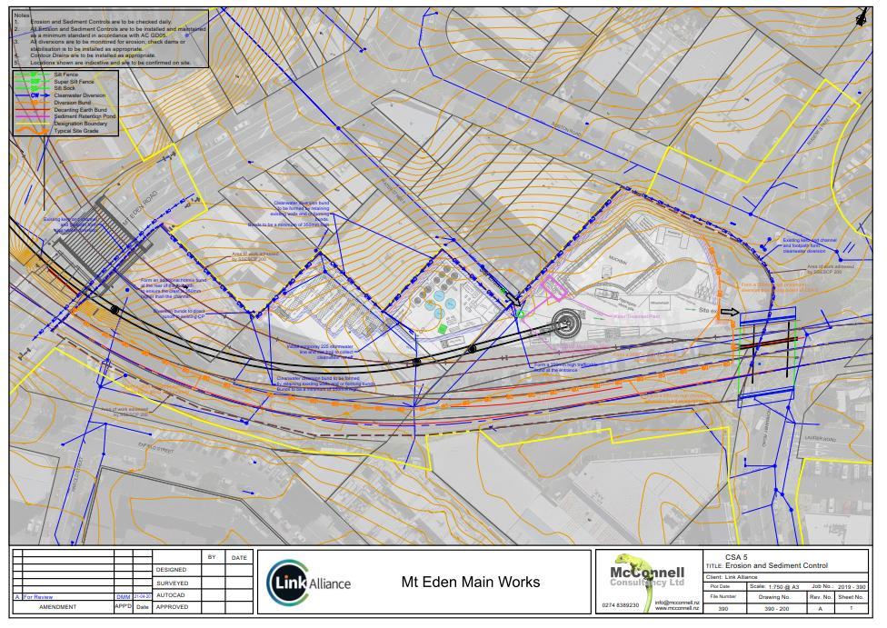
A further SSESCP has been prepared for the initial works being undertaken within CSA 5 and ACZ M2 between Normanby Road and Mt Eden Road.
These are provided in Appendix B of this ESCP.
1.6 ESCP Audience
The primary audience of this ESCP is the construction team management of the project and the Environmental Advisors, Project and Site Engineers.
This ESCP will also provide details of the erosion and sediment control management practices to be utilised on the main works to stakeholders including Auckland Council and the general community.
The required stage specific details are provided in the SSESCPs. It is these documents that will be used to provide the on-site staff with the information needed to ensure that the approved erosion and sediment controls are implemented
This separation of information and tailoring the included information to the intended audience is critical to ensuring that the erosion and sediment control measures are correctly designed, understood, implemented, maintained and improved.
Page 7 | Mount Eden Main Works
1.7 Relevant Conditions
Table 1-1 identifies the CRL resource consent conditions relevant to this ESCP and where they are addressed in the document.
Table 1-1 Resource consent conditions for ESCP and where addressed in this document
Land Use Consent R/LUC/2016/1890
Erosion and Sediment Control Plan (ESCP)
53 At least 20 working days prior to the commencement of construction within a CSA or ACZ, the Consent Holder shall submit to the Council (Team Leader Central Monitoring) for certification an ESCP which provides for the management of all bulk earthworks to minimise any discharge of debris, soil, sediment or sediment-laden water beyond the site to either land and/ or stormwater drainage systems.
54 The Consent Holder shall request the Council's (Team Leader Central Monitoring) determination as to whether the ESCP can be certified, in writing, within 10 working days of receipt of the ESCP. No construction activity shall commence until certification from Council is provided.
55 An ESCP shall include, but is not be limited to, the following matters:
• identification of construction zones and construction support areas;
• specific erosion and sediment control works for each Active Construction Zone (location, dimensions, capacity supporting calculations and design drawings), which should be in line with Industry Best Practice that will meet or exceed the performance of measures detailed in TP90;
• catchment boundaries;
• the timing and duration of construction and operation of control works (in relation to the staging and sequencing of earthworks);
• details relating to the management of exposed areas;
• reference to the Flocculent Treatment Management Plan and confirmation of erosion and sediment control measures necessary to give effect to that plan;
• reference to the Contaminated Soils Management Plan and confirmation of erosion and sediment control measures necessary to give effect to that plan; and
• monitoring and maintenance requirements, including information on complaint investigation and response procedures, training, and roles and responsibilities.
Section 5.0
56 Any change to an ESCP shall be submitted to the Council (Team Leader Central Monitoring) for certification. Section 1.9
57 The Consent Holder shall request the Council's (Team Leader Central Monitoring) written determination as to whether the proposed change can be certified, to be provided within 10 working days of submission of the change. No activity reliant upon a change to the ESCP can be undertaken until the change has been certified.
Section 1.9
58 The Consent Holder shall comply with the ESCP for the duration of the earthworks associated with the Project. Section 1.3
As Built Certification
65 Prior to the commencement of bulk earthworks, a certificate signed by a Senior Qualified Person shall be submitted to the Council (Team Leader Central Monitoring) to certify that the erosion and sediment controls (including diversion bunds, silt fences and sumps) have been constructed in accordance with the certified ESCP(s) as required by Condition 53 of this consent.
66 The certification from the Senior Qualified Person for these measures shall be supplied to the Council (Team Leader Central Monitoring) immediately upon completion of construction of those measures. Information supplied, if applicable, shall include:
• The contributing catchment area;
• The shape of structure (dimensions of structure);
• The position of inlets/outlets; and
Section 5.1.2
• The stabilisation of the structure. Section
General Performance Standards
67 The Consent Holder shall ensure that there shall be no deposition of earth, mud, dirt or other debris on any road or footpath resulting from bulk earthworks on the subject site. In the event that such deposition does occur, it shall immediately be removed. In no instance, shall roads or footpaths be washed down with water without appropriate erosion and sediment control measures in place to prevent contamination of the stormwater drainage system, watercourses or receiving waters. Section
68 The operational effectiveness and efficiency of all erosion and sediment control measures specifically required as a condition of resource consent, including the certified ESCP referred to in Condition 53, shall be maintained throughout the duration of earthworks, or until the Project site is permanently stabilised against erosion.
69 The site shall be progressively stabilised against erosion at all stages of earthworks activity, and shall be sequenced to minimise the discharge of contaminants to groundwater or surface water.
Section 1.3
Section 2.3
70 The Consent Holder shall ensure that the erosion and sediment control measures are constructed and maintained in accordance with TP90, except where a higher standard is detailed in an ESCP/FTMP, in which case the higher standard shall apply.
71 Sediment control measures shall be inspected on a weekly basis and after a significant storm event to ensure effective operation.
72 The Consent Holder shall ensure that all material removed from or delivered to the Project site shall be covered during transportation.
Review Condition for regional land use (earthworks) consent R/LUC/2016/1890
Specific conditions – discharge permit (contaminated land) R/REG/2016/1895 and land use consent R/LUC/2016/1890 (Contaminated Land and Resource Management (National Environmental Standard for Assessing and Managing Contaminants in Soil to Protect Human Health) Regulations 2011)
Contaminated Soils Management Plan
139 The Consent Holder shall manage all soil disturbance works to minimise any discharge of debris, soil, silt, sediment or sediment-laden water from the subject site to either land, stormwater systems or the receiving marine environment. The implementation of erosion and sediment controls shall be in accordance with the ESCP required by Condition 53
Advice Note: Measures such as covering the excavations overnight and during heavy rainfall, diverting overland flow around the works area, and appropriate treatment of any water collected in an excavation prior to the disposal may be required to comply with this condition.
141 To minimise the spread of contaminated material, any temporary stockpiles of the excavated contaminated material shall be located within the catchment of erosion and sediment controls for the site. All stockpiles shall be covered with either polythene or an equivalent impermeable material when the site is not being worked and during periods of heavy rain.
144 The Consent Holder shall implement the procedures for the management, treatment, temporary containment, testing, and disposal of groundwater and surface run-off water via the stormwater system in accordance with the report titled Auckland City Rail Link: Resource Consent Package 2: Aotea Station to North Auckland Line Construction and CRL Operation: Draft Erosion & Sediment Control Management Plan, dated 13 May 2016, prepared by Aurecon New Zealand Limited, and provided with the application.
145 Any perched groundwater, or surface run-off water, encountered within the excavation area requiring removal shall be considered as potentially contaminated, and shall either:
a. be disposed of by a licensed liquid waste contractor; or
b. pumped to sewer, providing relevant permits are obtained; or
Section 3.4
Section 3.4
Section 3.2
Section 3.5.5
Section 3.2 and CDWP
c. discharged to the stormwater system, provided testing demonstrates compliance with 50 times the Australian and New Zealand Environment Conservation Council (ANZECC) Guidelines for Fresh and Marine Water Quality (2000) for the protection of 95 percent of marine water species, and is free from petroleum hydrocarbons.
167 In the event that any CSA requires an increase in area, the following information shall be provided to the Team Leader –Central Monitoring whose certification shall be requested prior to implementation:
a. Plans and drawings outlining the details of the modifications; and
b. Supporting information that confirms how the proposal does not affect the capacity or performance of the existing structural and procedural controls.
168 The Consent Holder shall ensure that the following structural controls are constructed for the following catchment areas and design standards and they are completed prior to discharges commencing from the site:
Works /controls Device catchment area Design requirements
2 x Settlement Tanks located on CSA 4 Activity area of grout plant (400m2), and segment storage yard (2660m2) on CSA 4
Settlement Tanks sizing to be based on 2% of the contributing catchment
Inlet protection measures On all catch pits within CSA areas Design in accordance with Auckland Council Best Management Practice: Catch pit Protection Area (AC 2011).
2 x Settlement Tanks located in CSA 1, CSA 2, CSA 3, CSA 4 and CSA 5
All Active Construction Zones (ACZ) Settlement Tank sizing to be based on 2% of the contributing catchment
Noted
169 In the event that any minor modifications to the structural system are required, the following information shall be provided to the Team Leader – Central Monitoring whose certification shall be requested prior to implementation:
a. Plans and drawings outlining the details of the modifications; and
Section 1.9
b. Supporting information that confirms how the proposal does not affect the capacity or performance of the existing structural and procedural controls.
Mount Eden Main Works
1.8 Sustainability
The Link Alliance is seeking an Infrastructure Sustainability Council of Australia (ISCA) Infrastructure Sustainability (IS) Rating. Further details can be found in the main works CEMP and Sustainability Management Plan. Main works sustainability requirements that relate directly to this ESCP are included in Appendix A. These requirements are imbedded within the Delivery Work Plans and Management Plans for the main works to ensure that sustainability is a key focus and ‘the way we do things’.
In some cases, the IS requirements and sustainability goals enhance the designation requirements.
1.9 ESCP Review and Updates
This ESCP is a live document that will be reviewed at least annually, or as a result of a material change to the main works, or to address unforeseen erosion and sediment runoff effects arising from construction, or unresolved complaints. The ability to make changes to the ESCP is vital to maintain its effectiveness and relevance as the construction works progress.
Revisions to the ESCP will be made:
• As the Link Alliance considers necessary
• Promptly on any material change (including named personnel changes)
• If requested by Auckland Council
Any changes to this ESCP must be certified by Auckland Council prior to any on-site activity reliant upon the change commencing (as per resource consent conditions 56 and 57). Refer to the CEMP for further detail on the review and updating process.
As works progress on site, changes and modifications will be needed to control measures to ensure the effectiveness of these controls. To clarify the requirements of the above, the Environment and Sustainability Manager will determine whether the change is minor or major. This determines whether or not AC approval (via submission of a revised ESCP, or SSESCP) is required. Minor and major amendments are as follows:
Minor revision (no formal approval required):
• Repositioning bunds, silt fences, DEBs, SRPs, water treatment plants and discharge location where catchment size is not increased by more than 5% and device meets guidelines.
• Changing the dimensions of a SRP, DEB within the guidelines
• Areas disturbed under a “cut and immediately cover” methodology outside of existing controls < 750 m². There must be materials and resource on site that demonstrates a commitment to achieving this.
• The installation of additional controls where the approved control is not removed.
• Relocation of a Water Treatment Plant (WTP)
Major amendments (requiring AC approval):
• Removal of any control (SRP, DEB, bund, silt fence) – decommissioning.
• Addition of any new control not shown on ESCP plans.
• Replacement of a bund with a silt fence or vice versa.
• Construction of a device that does not meet the guidelines – i.e. SRP shape, forebay type, exceedance of SF criteria.
• Removal of a treatment device from the ESCP and increasing size of other devices to take that catchment.
• Replacement of a WTP with a WTP with a smaller treatment capacity.
2 Mt Eden Main Works Description
2.1
Overview of Works
The main works involve construction along several active work fronts concurrently within the Mt Eden area at any one time, to enable the redevelopment of the Mt Eden Station and establish the CRL tie-ins to the NAL Works will be carried out in a staged fashion. The construction staging, and methodologies are described in greater detail in the CEMP.
Within the main works area, there are already other works occurring in accordance with the Mt Eden Enabling Works (OPW60350039) and Normanby Road Early Works (OPW60351423) outline plan packages.
In summary, the main works involve:
• Ground improvements, in the form of deep soil mixing (contiguous piling and grout injection), within the NAL corridor between Mt Eden Road Bridge and Normanby Road;
• Bulk excavations and construction of retaining walls along the NAL to provide for the rail trenches and installation of new tracks. The excavation will encounter basalt, which will be removed via rock-breaking and blasting. In places, softer ground conditions are anticipated to be encountered, which may require the use of sheet piles;
• Construction of the eastern and western crossover structures that enable the CRL rail lines to tie-in to the NAL;
• Construction of the Porters Avenue and Fenton Street pedestrian and cyclist bridges.
• Construction of the Normanby Road grade separation bridge, including regrading of Normanby Road and realigning the Boston Road roundabout;
• Redevelopment of the existing NAL platform;
• Construction of the CRL platform and the foundations and building structures for the Mt Eden Station building and the ventilation building; and
• Operation of the TBM, including the conveying of spoil material from the tunnels and the refuelling and general maintenance of the TBM within CSA 4.
2.2 Construction Staging and Methodology
The main works will be divided into several stages within the various work areas.
Generally, the works along the NAL are divided into two stages to allow works on the northern (downmain) or southern (upmain) sections to correspond with the ‘Single Line Running’ of train services through the construction area.
Works within the Mt Eden station area are divided into 12 stages. Stages 1-4 have already been addressed in the Mt Eden Enabling Works outline plan package, and stages 5-12 will be undertaken as part of the main works. For the new Mt Eden Station building and ventilation building, construction of the foundations and building structures will be undertaken as part of stages 5-12, while the finishing of the buildings, including internal and external fittings, will be completed as part of the future public realm reinstatement.
The construction staging, and methodologies are described in sections 2.3 and 2.4 of the CEMP.
1.1.1.
Active Construction Zones
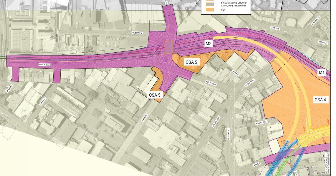
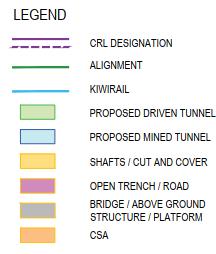
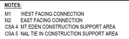
The main works consist of Active Construction Zones1, as depicted in Figure 2-1 (Eastern end and in Figure 2-2 (Western end) and listed below:
• M1 – West Facing Connection (WFC) of the NAL/Western line from Mt Eden Road Bridge to Dominion Road. This includes the Construction Support Area 4 (CSA4).
• M2 – East Facing Connection (EFC) of the NAL/Western line from Boston Road to Mt Eden Road Bridge, i.e. including the Eastern Facing Connections. This includes the Construction Support Area 4 (CSA5).
1 Aotea to North Auckland Line Final Approved Plans S133A 2 – CRL-AOT-RME-AT-PLN-028624, 17 November 2016
Figure 2-1 Main Works ACZ and Construction Support Areas (CSA4 and CSA5) – Eastern End
2.2.1 Construction Support Areas
There are three areas that have been identified as Construction Support Area (CSAs) as part of the main works:
• CSA 5 also referred to as EFC2 CSA located at 14-22 Boston Road, 11 Water Street and 28 Mt Eden Road;
• CSA 4 between Ngahura Street, Nikau Street and Mt Eden Road also referred to as MTN CSA; and
• Western end of NAL CSA 5 near 1A Porters Avenue, also referred to as WFC CSA.
The CSA 4 and CSA 5 (EFC2) have already been established during the Normanby Road early works and Mt Eden Enabling Works. The western extension of CSA 5 will also be established during the main works as part of the WFC site set up.
Generally, EFC activities will be supported by CSA 4 and MTN and WFC activities will be supported by CSA5. It is noted that some of the plant and activities in CSA5 may be used for activities related to EFC works. Further detail is provided in the CEMP.
2.3 Duration of Works
The works covered by this ESCP will commence in April 2020 and continue until completion of works, June 2023
Figure 2-2 Main Works ACZ and Construction Support Areas (CSA4 and CSA5) – Western End
2.4 Site Description
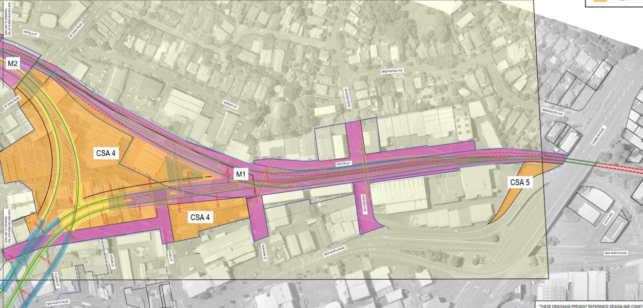
The main works will be undertaken near the existing Mt Eden Station and along the NAL, in an existing urban environment. The main works area is generally bounded by the NAL (south), State Highway 1 (east), Dominion Road (west), and Nikau Street (north) (refer Figure 2-3). The main works will include construction activity along Nikau Street, Ruru Street, Porters Avenue, Fenton Street, Haultain Street, Ngahura Street, Flower Street, Shaddock Street, Mt Eden Road, Normanby Road, Boston Road and Nugent Street.
CRL Designation 2500-6 KiwiRail Designation 6300
Figure 2--3: Site and extent of main works
3 Design Philosophy and Principles
3.1 Existing Conditions and Receiving Environment
The main works area that is the subject of this ESCP is detailed in Section 2.4 of this ESCP.
Broadly this is the Mt Eden Station area and the NAL corridor between Dominion Road and SH1
The main works CSAs and ACZs total approximately 10.5ha in area. These areas are further defined within Section 2.2.2 of the CEMP.
The area surrounding the proposed main works is a fully developed urban environment with nearly 100% impervious cover.
Of the main works area, approximately 2.0ha is rail corridor including ballast and impervious station and road crossing areas. The remaining 8.5ha comprises a fully developed urban environment including buildings, roads and carparks. There are minimal existing vegetated areas within the main works area (approximately 5,500m2).
The stormwater network and associated overland flowpaths discharge ultimately to Motions Creek and the upper Waitematā Harbour
3.2 Discharge Standards
The discharge of water from the site is to be managed in accordance with the Water Quality Assessment that was submitted as part of the CRL Aotea Station to North Auckland Line resource consent application (Condition 59 R/LUC/2016/1890).
This assessment summarised that:
“Stormwater generated from impervious surfaces within the CSAs will be discharged directly to the stormwater system. Quality will be managed through on-site work practices and filters at existing catchpit entries within the CSA.
Groundwater and stormwater (where applicable) collected in ACZs will be pumped to settlement tanks located within adjacent CSAs. Disposal will occur to the stormwater system if key indicators of quality demonstrate it is suitable for disposal. Considering the groundwater quality issues identified in some areas of the CRL construction, supplementary treatment may be required, e.g., pH adjustment, or secondary treatment for trace metals removal.
All ACZs with vehicular access will have wheel washes. Water from each wheel wash will be pumped to treatment facilities in the adjacent CSA”
This ESCP, and associated SSESCPs, include control measures to ensure compliance with this assessment
Additionally, a Water Discharge Quality Monitoring Programme (WDQMP) has been developed which specifies the monitoring to be undertaken and the discharge triggers to be monitored. This WDQMP is included within the FTMP (refer Appendix C of this ESCP)
3.3 Sources of Contamination
Resource consent Condition 145 states:
Any perched groundwater, or surface run-off water, encountered within the excavation area requiring removal shall be considered as potentially contaminated, and shall be either:
a. be disposed of by a licensed liquid waste contractor; or
b. pumped to sewer, providing relevant permits are obtained; or
c. discharged to the stormwater system, provided testing demonstrates compliance with 50 times the Australian and New Zealand Environment Conservation Council (ANZECC) Guidelines for Fresh and Marine Water Quality (2000) for the protection of 95 percent of marine water species, and is free from petroleum hydrocarbons.
In regard to this ESCP, there are two classes of contaminants to be considered
3.3.1 Sediments
These contaminants are specifically the sediments that are the result of surface earthworks and tunnelling earthworks.
Runoff (including groundwater) contaminated with sediments will typically be discharged (following appropriate removal of the sediments) to the stormwater system in accordance with condition 145(c.) set out above.
The control of this sediment laden water will be undertaken in accordance with the details in Section 5 of this ESCP
3.3.2 Other contaminants
There are a range of additional contaminants that already exist on the site and others that will be utilised (and managed) on site as part of the construction activities.
The Contamination DWP (C DWP) has undertaken sampling and testing of the existing soils and has determined that the upper levels of fill material, particularly within the rail corridor, have contaminants above background levels (AC TP153), and will therefore require disposal as managed fill. Any groundwater and or surface water which comes into contact with this material is not, however, considered to exceed the discharge standards within the WQDMP included in the FTMP.
The contaminants utilised by the construction activities include:
• Fuels and oils
• Concretes and grouts
• Form oils and other sundry construction products
• For a full list of contaminants to be utilised on site refer to the ITA EMP in Appendix Q of the CEMP.
The contaminant that is anticipated to have the greatest effect during the main works (excluding sediment) is the use of concrete and grouts and the associated high pH runoff associated with these activities.
Runoff (including groundwater) containing contaminants, excluding sediment, will be discharged to stormwater provided that testing demonstrates compliance with the requirements of the WQDMP. Where this compliance cannot be achieved, the discharge will be to sewer or as an offsite disposal. The determination of disposal method will depend on the nature of contaminants present and volume.
3.4 Contamination Specific Erosion and Sediment Control
As detailed within the CDWP, any excavated contaminated material will be removed directly from site wherever practical. Where this is not practical any temporary stockpile will be bunded and covered (in accordance with the requirements of the CDWP). The runoff from this material will be impounded and will be discharged to trade waste or removed from site.
Specific stockpile measures are further detailed in section 3.5.5 of this ESCP and in section 5.6 of the CDWP
3.5 Erosion and Sediment Control Principles
3.5.1
General
All erosion and sediment control measures and methodologies utilised on site will be designed, implemented and maintained in accordance with Auckland Council Guideline Document 2016/005 “Erosion and Sediment Control Guide for Land Disturbing Activities in the Auckland Region” (GD05).
GD05 is the updated version of Auckland Council Technical Publication No.90 (TP90) which is referenced in conditions 55 and 70 of the A2N resource consent.
3.5.2
Erosion Control Principles
Erosion control principles will remain the same as for any project, the first principle being to minimise the sediment generated by minimising erosion. This will be achieved in the following ways:
• Minimise disturbance: Only work those areas required for construction to take place.
• Stage construction: Carefully plan works to minimise the area of disturbance at any one time.
• Protect steep slopes: Where steep slopes exist within the works area, ensure that these are protected - as steep slopes are prone to erosion.
• Protect watercourses: There are no freshwater watercourses within the main works area
• Stabilise exposed areas rapidly: With hardfill and/or final surfacing
• Install perimeter controls: Divert clean water away from areas of disturbance and divert runoff from areas disturbed to sediment control measures.
3.5.3
Sediment Control Principles
As with erosion control, the sediment control principles will remain the same as for any project, specifically to intercept any sediment laden flows and discharge them via a sediment retention device.
Notwithstanding the above, due to the specifics of the main works, and in particular the final contours associated with these works, the gravity discharge of surface runoff from the majority of the main works area will be impractical.
As the works within the NAL are undertaken they will form a series of self-contained excavations. These excavations will only be able to be dewatered via pumping.
As the works associated with the tunnel portal progress, this area will become the low point for the majority of the main works area. Surface runoff and groundwater that has collected at this point will be collected and pumped to one of the sediment control devices.
This requirement to pump and the space restrictions on the site dictate that traditional sediment retention devices, specifically Sediment Retention Ponds (SRP) and Decanting Earth Bunds (DEB) will not be appropriate for the majority of the site area, particularly in the later stages of the works.
The sediment laden water to be controlled on site will be directed to a Water Treatment Plant (WTP) prior to discharge.
There will be a primary WTP which will be located in CSA 4, in the north-eastern part of the Technical Area (refer Figure 2-5 in the ITA EMP). This plant will control water from the tunnelling operation and from the general earthworks within CSA 4 and the M1 ACZ
A secondary WTP at CSA 5 is located adjacent to the entrance off Water Street. This plant will control water from the operations within CSA 5 and the M2 ACZ.
These primary and secondary water treatment plants will be supplemented by smaller WTPs, which will be relocated around the site as appropriate to control runoff that cannot practically be directed to the primary or secondary WTP
The specific details of each WTP will be detailed within the SSESCP for each area of work.
Further details of the WTPs is given in section 4.1.2.1 of this ESCP.
3.5.4 Settlement Tanks
Resource consent Condition 168 requires that ‘Settlement Tanks’ be utilised to control runoff from the grout plant and segment storage yard.
Condition 168 also requires that 2 x ‘Settlement Tanks’ be installed for all ACZ, with the Settlement Tank sizing based on 2% of the contributing catchment.
‘Settlement Tanks’ are not defined within GD05, the consents or the draft ESCP submitted with the resource consent application. This is largely a generic term for a tank which controls sediment, whether the method of treatment is by settlement or filtration.
The SRPs and DEBs utilised as part of the sediment control measures achieve sediment removal via settlement and will be sized to the 2% criteria (2m3 of storage for each 100m2 of contributing catchment) as a minimum standard. The utilisation of SRPs or DEBs therefore meets the requirements of Condition 168.
The design of the Water Treatment Plants, (see section 4.1.2.1) is based on flow volumes and rates rather than a storage volume based on contributing catchment area Notwithstanding this, storage in accordance with the 2% criteria (2m3 of storage for each 100m2 of contributing catchment) will be provided within the WTP and or associated storage / buffer tanks.
3.5.5 Management of Contaminated Flows
As noted previously a key component of sediment control will be the management of water, both surface and groundwater, which has come into contact with contaminated materials.
These contaminated materials are both the existing in-situ contaminants and those contaminants that are a result of the construction activities, in particular the use of concrete products which have the potential to elevate the pH of water
3.5.5.1 Contaminated Soils
Areas of potential contamination that require specific management are identified within the CDWP.
For ease of interpretation and based on the risk profile, the geology of the construction areas has been split (within the CDWP) into three groups, ballast, unnatural soils (engineered and nonengineered fill) and natural soils.
The CDWP has summarised the contamination status of these soils as:
3.5.5.1.1
Ballast
Ballast is considered to be free of contaminants if no odours or staining are present and may be reused as part of construction. If removed from site and if no odours or staining are present it can be disposed as cleanfill, subject to landfill acceptance.
Any ballast that has odours or staining, particularly within the current Mt Eden Station area, will require disposal to a suitable disposal location. Ballast is suitable for permanent or temporary reuse during construction.
There is a potential risk, albeit low, that ACM fragments may be present within the ballast. It is recommended that a further inspection is undertaken again prior to disturbance of the ballast and any ACM identified is reported and removed by a licensed specialist.
3.5.5.1.2
Unnatural Soils (Fill)
Fill is present across the site varying in depth, but typically present between the surface and approximately 4.0 m bgl. Based on the available results, fill materials cannot be disposed as cleanfill and will require disposal to either a managed or licenced landfill. Disposal to managed fill is subject to compliance with the spoil meeting the acceptance criterial of the disposal location.
3.5.5.1
3 Natural Soils
Following removal of all fill material, the underlying natural material, if free from staining or odour, is suitable for disposal as cleanfill. The receiving facility may require confirmatory testing, which should be undertaken in accordance with the soil sampling procedures detailed in Section 5.11 of the CDWP. Where practical, fill materials will be kept separate from natural material. These will be stored in separate bunds if stockpiling is to take place. Where mixing occurs of these materials, all material will be considered as managed fill.
3.5.5.1.4 Asbestos Contaminated Soils
The results of the limited asbestos in soil investigations undertaken specifically within the former South Pacific Timber site at Ruru Street indicate the presence of trace asbestos in fill soils. Disturbance of surficial fill material on the South Pacific Timber site shall be undertaken, as a minimum, as Unlicensed Asbestos Works as defined in ‘NZ Asbestos in Soil Guidelines’, unless further testing is undertaken to justify that the controls are not required.
3.5.5.1.5
Bentonite
Bentonite will be used as part of the Diaphragm Wall (D Wall) construction. Bentonite itself is a clay and is considered a cleanfill material.
However, soils that have come into contact with bentonite as part of theD-wall operations or other piling operations which utilise bentonite, pose a particular challenge for sediment control. This is related to the properties of bentonite for which it is utilised, specifically that it remains in suspension. The result of this is that runoff which contains bentonite needs to be isolated from other runoff and controlled separately.
Typically, this treatment is limited to recycling and removal from site.
Details of the specific Bentonite Plant management are detailed in section 5.1 of the ITA EMP
3.5.5.2
Water Management
3.5.5.2
1 Stormwater
All practical steps must be taken to keep stormwater and surface run off separated from ground and perched water. Separation and diversion of clean stormwater away from areas of ground disturbance is standard practice for any earthworks activity but becomes more important where contaminants are present. To minimise the potential for clean stormwater to encounter contaminated soil, the stormwater and sediment controls detailed in this ESCP shall be implemented.
3.5.5.2 2
Interaction between water and soils
All water that has interacted with exposed spoil including ground, perched and surface run off water will be managed and disposed of via the following methodology:
• Piped or pumped to a sediment control system or WTP;
• Further treatment (i.e. flocculant additives, pH adjustment) in accordance with the procedures detailed in the FTMP for the works; and
• Testing in accordance with the Water Quality Discharge Monitoring Programme (WQDMP) included in the FTMP, to confirm compliance with the criteria for discharge to stormwater.
3.5.5.2 3
Additional Considerations
As noted in Section 3.5.5.2.1, the primary measure for controlling contaminated flows is to isolate the sources of contamination from surface runoff, in accordance with standard erosion control principles.
The secondary measure will be to isolate contaminated flows from other surface runoff generated within the works area (including surface runoff contaminated with sediment). The purpose of this isolation is to limit the volume of contaminated flows that need to be controlled.
This isolation will allow the subsequent control measures to be implemented which best manage the contaminant(s) of concern. Specifically, this isolation will allow further control in accordance with resource consent condition 145 Subject to the nature of the contaminant this may require off-site disposal, discharge to trade waste or discharge to stormwater following appropriate treatment.
The primary control measure for water with a high pH as a result of concrete or grouting works is for it to be discharged via a Water Treatment Plant that includes acid dosing or CO2 injection to reduce pH.
Where the contaminated flows cannot be controlled to a standard that allows discharge to stormwater, these flows will be collected and disposed of by a licenced liquid waste contractor or discharged in accordance with the Trade Waste Permit (once obtained)
4 Overall Erosion and Sediment Control Approach
The earthworks to be undertaken are relatively simple and are broadly a cut to waste operation with excavated material being removed from site. As much as practical, this excavation will be undertaken directly into road trucks for removal from site. In confined areas, the material may need to be initially loaded into small onsite trucks which will transport it to a ‘surge’ stockpile, where it will be temporarily stored until it can be loaded into road trucks for offsite disposal.
The excavation will also encounter basalt, which is to be blasted in order to expedite the works and minimise the amount of rock-breaking required. Where practical and suitable this broken basalt will be crushed on site for reuse
4.1 Specific Erosion and Sediment Controls
The erosion and sediment controls detailed within this ESCP are based on the current construction methodologies and knowledge of ground conditions, underground utility locations etc. As the construction methodologies are refined and a greater knowledge of ground conditions is gained, the specific erosion and sediment control details and methodologies for each stage contained in the SSESCPs will be updated
Initial SSESCPs are included as Appendix B. Revisions to these SSESCPs will be provided to Auckland Council for certification in accordance with resource consent conditions 56 and 57
The following sections detail the overarching design criteria for the main works, which are reflected in each of the SSESCPs (Appendix B)
As detailed in section 3.5 of this ESCP, the overarching erosion and sediment control principle of diverting cleanwater and controlling dirty water will apply.
4.1.1 Cleanwater Diversions
In accordance with the resource consents, cleanwater diversions are required to divert runoff from the 5% annual exceedance probability (AEP) storm (20-year event) with 300mm freeboard. The insurance for the project requires that the 50-year event is diverted, as a result all diversions will be designed to divert runoff from the 50 year event.
A large proportion of the site is bounded by existing roads. Where practical the existing kerb and channel and associated stormwater network will be retained. In regard to the above capacity, these kerbs will have to be lifted by a minimum of 300mm to ensure compliance.
To facilitate the diversion of clean water a key component of the utility relocation programme will be to ensure that the existing stormwater network remains operational.
As part of the preparing the SSESCPs, an assessment is made of the ability of the existing kerb and channel and stormwater network to divert the existing flows. This assessment will identify where kerbs have to be extended across redundant roads and where temporary cesspits or other stormwater inlets are needed.
This assessment also highlights where temporary or permanent stormwater diversions are required and the priority of those diversions. Where the permanent stormwater diversions cannot be implemented temporary diversions will be constructed.
A limiting factor of the capacity of stormwater diversions may be the capacity of the existing downstream network. This will be considered in the design of the cleanwater diversions and in the design of the downstream sediment controls, where overflows from the cleanwater diversions may occur.
Where the existing kerbs as not suitable as diversions, bunds will be installed. The specific design of these bunds will take into account the contributing catchment and the location of the bunds.
Where these bunds are required on a sealed surface (road, carpark, footpath etc) hotmix bunds or low concrete block walls will be utilised.
Where the diversions are required on grassed areas, traditional topsoil bunds will be installed.
Between the stages of work within the rail corridor, the diversion of runoff from outside of the active work area will not always be practical due to the pervious nature of the ballast. In these areas the additional cleanwater catchment area will be accounted for within the design of the sediment controls for that specific area.
4.1.2 Sediment Control
As noted in section 3.5.3 of this ESCP, the primary sediment control for discharges from the site will be Water Treatment Plants (WTP).
The water treatment process will include the use of either chemical or non-chemical flocculants (the latter being preferred if effective) as well as pH dosing and will be undertaken at the WTP.
If the quality of the discharge is not deemed appropriate for stormwater discharge, it will be discharged to sewer in accordance with resource consent condition 145 (b) (provided it complies with a Trade Waste Permit previously applied for and authorised by Watercare), or disposed of by a licenced liquid waste contractor (in accordance with resource consent condition 145 (a))
There will be a primary WTP which will be located in CSA 4, in the north-eastern part of the Technical Area . This plant will control water from the tunnelling operation and from the general earthworks within CSA 4 and the M1 ACZ.
A secondary WTP at CSA 5 is located adjacent to the entrance off Water Street. This plant will control water from the operations within CSA 5 and the M2 ACZ.
These primary and secondary water treatment plants will be supplemented by smaller WTPs, which will be relocated around the site as appropriate to control runoff that cannot practically be directed to the primary or secondary WTP.
The specific details of each WTP will be detailed within the SSESCP for each area of work.
4.1.2.1
Water Treatment Plants
The design of the WTPs considers two primary criteria, the nature of the water to be controlled and the volume of water.
4.1.2.1.1
Water Quality
The water from the general earthwork areas will require treatment to remove sediment and, in some instances, will require pH buffering where the water has an elevated pH as a result of concreting, grouting activities or ground improvement operations
The water from the tunnelling operation will also contain sediment and will require pH buffering. This water however will be included within the larger discharges from the tunnelling activity which will include the slurry as a result of the tunnelling operation.
As detailed in section 3.5.3, the majority of water to be controlled from the earthwork areas and activities will be pumped to WTPs. These WTPs will be designed to control the runoff from the specific areas and activities from which they will receive pumped flows. This design will consider a number of factors including:
• Construction activities – in regard to how much soil is disturbed (area and volume)
• Construction activities – in regard to how the soil is disturbed (traditional excavation, piling, tunnelling)
• Construction activities – in regard to additional contaminants (cement, lime, bentonite, slurry mixes)
• Soil types
These factors will determine the specific design of the WTP in order to control the pumped flows to ensure the final discharge complies with the requirements of the WQDMP.
4.1.2.1.2
Water Quantity
Traditional sediment retention devices (SRPs, DEBs) are designed according to a contributing catchment area, rather than any specific flow rate.
This is reflected in the 2% storage criteria within resource consent condition 168
GD05 requires that diversion bunds have the capacity to direct runoff from the 5% AEP to sediment retention devices, however due to the operation of these devices the treatment efficiency declines dramatically once the primary and emergency spillways are activated. Typically, this occurs for rainfall events in excess of a 50% AEP.
The capacity component of the design of the WTPs for each area will be based on the capacity required to allow the area of work to be pumped dry as quickly as possible. This has been determined from historical rainfall events over the past 6 years. For rainfall events in excess of this capacity, provision is made for additional storage at the WTP. For extreme events, excess water will be stored within the site. This will be allowed for by temporary bunding and or excavation undertaken prior to these rainfall events. The outcome of this is that all discharges from the site will be controlled to the required discharge standards prior to discharge.
The volume of water to be controlled by each WTP will be based on the following:
• There are two sources of water to be considered, groundwater and surface water.
• Groundwater flows will be taken from the groundwater assessments for the specific areas from which water will be pumped to the WTP
• The volume of surface water will be based on the surface area of the sites.
• The second factor in determining the volume of surface water is the rainfall. Rainfall data has been obtained from the Auckland Council Rainfall Monitoring Station at Albert Park, approximately 2km from Mt Eden Station (refer Table 1). Daily rainfall data from the last 6 years has been used in the assessment.
• This data has been used to determine the daily maximum rainfall that has occurred in the last 6 years.
• This has shown that the maximum daily rainfall in the last 6 years was 81mm (5 April 2017).
• The average maximum daily rainfall in the last 6 years was 38mm
• As the maximum daily rainfall (81mm) was significantly higher than the next maximum daily rainfall (64mm), it has been decided that using a design maximum daily rainfall of 61mm (75% of daily maximum) provides a ‘likely high rainfall’ to determine the likely rainfall volumes which will need to be frequently discharged.
This rainfall depth (61mm) will be used to determine the volume of surface runoff.
This surface runoff will be combined with the anticipated groundwater to determine the total volume of water which may need to be discharged on a daily basis.
This daily volume will then be converted to an hourly discharge rate over 24 hours to determine the minimum treatment capacity of the WTP.
This treatment capacity will then be used to determine what additional storage will be needed at the WTP or within the site to contain runoff from various rainfall events
The rainfall events considered will be the 50%, 20%, 2% and 1% AEP events (2, 5, 20 and 100 year).
The 24-hour rainfall depths for these have been determined from the NIWA High Intensity Rainfall Design System (HIRDS) in Table 2:
AEP Event 24 Hr rainfall depth
Table 2 AEP Rainfall Depth
Table 1 Maximum Daily Rainfall (mm) - Auckland Councils Rainfall Monitoring Station - Albert Park
It is to be noted that the 20%, 2% and 1% rainfall events are unlikely to be un-forecast events which will allow the site to be prepared ahead of these events.
This preparation will include the provision of additional storage, as required, which will be achieved by bunding or excavation as required. Note in the majority of instances this will simply involve allowing existing excavated areas to pond.
These required storage volumes will be included in the SSESCP for that area.
4.1.2.2 Primary Water Treatment Plant
The primary WTP will be located in CSA 4, within the north-eastern part of the Technical Area. This plant will control water from the tunnelling operation and from the general earthworks within CSA 4 and the M1 ACZ.
The earthworks area that will be controlled by the primary WTP is approximately 3.75ha in area
The earthworks in this area include:
• Traditional cut to waste,
• Bored piling operations
• Rock Breaking
• Trenching for service installations
The soils in this area that have been encountered to date are typically silty clays. As the depth of the excavation increases, it is expected these soils will progress through Tauranga Group alluvium, clayey to sandy silts. The rock breaking will be undertaken within the basalt of the area.
These soils will be considered in the final design of the WTP.
As noted in Section 4.1.2.1.2 above, the volume of water to be controlled needs to be considered in the design of the WTP.
The CSA 4 area (3.5ha) is expected to generate approximately 17.5m3/hr of groundwater.
The 61mm daily rainfall event will generate a further 2,135m3, per day (89m3/hr).
The combination of the above results in a requirement to be able to control 106.5m3/hr (2,556m3 per day)
The additional storage required for various storm events is as follows:
The additional storage for the 50% and 20% AEP events will be provided within a buffer tank installed as part of the WTP. The additional storage required for the 2% and 1% AEP events will be provided on site.
This control capacity will be a minimum capacity. Additional capacity will be assessed and may be utilised to control discharges from additional areas. Where additional areas are to be controlled by the primary WTP, this will be detailed in the SSESCP for that additional area.
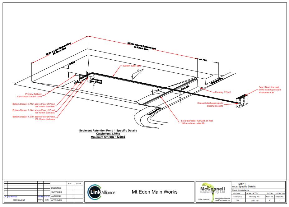
The design of the primary WTP is still being determined and will be confirmed within the final SSESCP for the work area (an interim SSESCP utilising a traditional SRP is attached in Appendix B).
Current design criteria:
- De-sanding units (cyclone and screening)
- Radial thickener: flocculant and coagulant with automatic regulation MES and flow with siphon separation (10 meter), may be equipped with floating pump to remove floating element (oil, foam etc)
- Filter presses: to dry the muds,
- pH correction: CO2 bubble injection in high height tank (> 5 meters) or Acid
- Capacity: 300m3/hr
- Buffer tank (storage and decantation) – 12,5 meter / 9,5 meter – around 1000 m3
- Clarification if needed: post decantation tank or/and Sand filters
4.1.2.3 Secondary Water Treatment Plant
A secondary WTP at CSA 5 is located adjacent to the entrance off Water Street. This plant will control water from the operations within CSA 5 and the M2 ACZ
The earthworks area that will be controlled by the secondary WTP is approximately 0.75ha in area.
The earthworks in this area include:
• Traditional cut to waste,
• Bored piling operations
• D-Wall construction
• Ground improvement, deep soil mixing with cement
• Trenching for service installations
In this area, discharges from the D-Wall activities will be isolated and kept separate from the general site runoff.
The undertaking of ground improvements will elevate the pH of discharges in this area. This will be monitored as part of the WTP operation and will be balanced, as required through acid injection.
The soils in this area that have been encountered to date are typically silty clays As the depth of the excavation increases it is expected these soils will progress through Tauranga Group alluvium, clayey to sandy silts.
These soils will be considered in the final design of the WTP.
As noted in Section 4.1.2.1.2 above, the volume of water to be controlled will be considered in the design of the WTP.
The CSA 5 and the M2 ACZ area (0.75ha) is expected to generate approximately 3.5m3/hr of groundwater.
The 61mm daily rainfall event will generate a further 458m3, per day (19m3/hr).
The combination of the above results in a requirement to be able to control 22.5m3/hr (540m3 per day).
The additional storage required for various storm events is as follows:
The additional storage for the 50% AEP event will be provided within a buffer tank installed as part of the WTP. The additional storage required for the 20%, 2% and 1% AEP events will be provided on site.
This control capacity will be a minimum capacity. Additional capacity will be assessed and may be utilised to control discharges from additional areas. Where additional areas are to be controlled by the secondary WTP, this will be detailed in the SSESCP for that additional area.
The secondary WTP will consist of Lamella Clarifiers, and will include provision for flocculent dosing to improve efficiency and acid injection for pH buffering
4.1.2.4
Additional Water Treatment Plants
The additional WTPs will be Lamella Clarifiers that will be located as required to control runoff from specific areas where the pumping of flows from these areas to the primary or secondary WTPs is impractical
These Lamella Clarifiers will include provision for flocculent dosing to improve efficiency and acid injection for pH buffering. Additional storage tanks will be provided as required
4.1.2.5
Chemical Treatment
The attached Flocculant Treatment Management Plan (refer Appendix C) has been prepared to identify measures that will be implemented to enhance the effectiveness of the erosion and sediment control measures utilised on site.
This FTMP also includes the Water Quality Discharge Monitoring Programme (WQDMP).
As detailed above during the Mt Eden Main Works the majority of sediment control will be achieved utilising WTPs.
These WTPs will include provision for flow triggered flocculent dosing
The specific flocculant to be used and dose rate will be determined by bench testing that will be undertaken during setup of the water treatment plant and prior to commencing operation.
As works progress additional testing will be undertaken as required by changing soil types.
4.1.3 Wheel Washing
There will be a large number of vehicles exiting the site, such as private cars and contractor vehicles, as well as larger trucks and truck and trailers delivering materials and removing spoil from the site.
These traffic movements have the potential to result in mud and dirt being deposited on public roads.
The primary measure to mitigate this risk is to manage the CSAs so that the majority of vehicles remain on stabilised surfaces (aggregate, concrete, seal) so that they do not become dirty. To achieve this stabilised parking areas will be provided at the site office. Laydown areas and delivery areas will also be stabilised.
Bulk excavated material will be removed from the site utilising a ‘surge’ stockpile. This surge stockpile will be in a bunded area adjacent to a stabilised surface. The truck and trailers which will remove material from the stockpiles will remain on a stabilised surface to prevent their wheels from becoming dirty. This surge stockpile area(s) will be actively managed so that if any material is dropped during the loading process it is removed before the truck leaves to prevent the truck driving through this material.
As a contingency, at the exit from the CSAs a wheel wash will be installed to ensure that in the event that all other site management controls have been ineffective and a vehicle does have dirty wheels, it can be cleaned before exiting onto public roads
4.1.4
Material Transport
All material removed from or delivered to the main works area will be covered during transportation to prevent discharges of dust and to further minimise the potation for material to be deposited onto public roads.
4.1.5 Utility Relocations
A number of utility relocations will need to be undertaken as part of the construction activities. A number of these relocations will need to be undertaken ahead of the main construction activities, additional relocations may also be needed in isolated areas separate to the main construction activities and/or areas.
Erosion and sediment runoff associated with utility relocations will be managed in a traditional manner, largely influenced by the magnitude of the diversion activity.
The majority of these utility diversions will be within existing roads or footpaths and will, typically, require trenching.
4.1.5.1 Cleanwater Diversions
Where practical existing kerb and channel will be retained as a cleanwater diversion. Where the works are within pavement areas hotmix bunds or 300mm filter socks will be used to divert surface runoff around the work areas.
Where existing kerb and channel extends through the work areas, the above hotmix or filter sock bunds will be used to divert this cleanwater around the works. Where the grades of the area prevent this, sandbag dams will be installed in the kerb and channel above the work area to direct the channel flows into a 150mm PVC pipe(s) to convey this water through the site.
During the relocation / diversion of the stormwater network, the new sections of stormwater pipe will be installed ‘offline’ with the connections made to the existing network as a final operation. Where this is not possible over pumping will be required.
4.1.5.2 Sediment Control
As noted, the majority of the utility relocations will require trenching. The sediment control for this will therefore be predominantly as the result of pumping.
The treatment of these pumped flows will be in part determined by the volumes encountered. For smaller flows and where there is room for a Turkeys Nest, this device will be the primary sediment control device for these works.
Where there is insufficient room for a Turkeys Nest, any sediment laden flows will be pumped and or transported by small tanker to a treatment device (most likely the primary WTP) within CSA 4.
As part of initial planning for utility relocation works an assessment will be made of anticipated groundwater flows. This assessment will be based on groundwater knowledge at the time including information from previous service relocations. As the works progress this will be supplemented by site observations.
Where the volumes of dirty water (most likely as a result of high groundwater flows) exceed the capacity of a Turkeys Nest an additional WTP will be utilised. Where there is insufficient room for such a device a pumped network will direct these flows to the main site.
These volumes will be monitored by the Site Engineer and Environment and Sustainability Manager or their delegated representative, to ensure that any additional control measures are implemented before existing controls become insufficient.
5 Monitoring and Maintenance
5.1 Monitoring
The monitoring and inspection of the work areas will be undertaken in five main stages:
1. Pre-construction inspection of erosion and sediment controls;
2. As-built inspection of erosion and sediment controls;
3. Informal random Inspections of erosion and sediment controls;
4. Regular recorded inspection of erosion and sediment controls; and
5. Final Inspection of erosion and sediment controls.
5.1.1 Pre-Construction Inspection
A pre-construction inspection will be carried out to ensure that the controls detailed on the SSESCP drawings for each area are appropriate and will be effective. This inspection will also be used to confirm that the site foremen for the areas are fully aware of the requirements in each specific areas.
The pre-construction inspection will be undertaken by the Environment and Sustainability Manager, or their delegated representative, relevant Site Foremen and Engineers.
5.1.2 Certification Inspection
The certification inspection will be undertaken as soon as the controls detailed on the SSESCP drawings have been constructed.
This certification will include but not be limited to the dewatering and treatment devices, stabilised construction entrances, cesspit protection and clean and dirty water diversions.
The information included in this certification will include (as appropriate):
• Contributing catchment area;
• Treatment capabilities and capacities;
• Shape and capacity of the structure;
• Position of Inlets and outlets;
• Stabilisation of the structure; and
• A statement regarding the appropriateness of the device with respect to GD05.
The certification inspection will be undertaken by the Environment and Sustainability Manager. A copy of this certification will be forwarded to the Team Leader Central Monitoring prior to earthworks within the contributing catchment of that device.
5.1.3 Informal Random Inspection
The informal random inspections will verify that the approved controls are installed correctly and that they are operating efficiently. Any maintenance issues will be immediately rectified. Any minor adjustments to the erosion and sediment control measures will be determined at this time.
These inspections will typically be undertaken by the Environment and Sustainability Manager or appropriate delegate.
5.1.4 Regular Recorded Inspections
Regular recorded inspections will be undertaken weekly to verify that any maintenance requirements are being carried out and that these requirements are being completed in an appropriate timeframe. These inspections will also provide an opportunity to fine tune any existing controls to improve the efficiencies of these controls.
The regular recorded inspections will typically be undertaken by the Environment and Sustainability Manager or appropriate delegate. These inspections are in addition to regular Auckland Council compliance monitoring visits to the site.
Additional inspections will be undertaken within 24 hours of rainstorm event that are likely to impair the function or performance of the erosion and sediment controls (i.e. a 20-year ARI or greater).
5.1.5 Final Inspection
The final inspection will be undertaken on areas that have been stabilised in order to verify that the erosion and sediment controls can be removed.
The final inspection will be undertaken by the Environment and Sustainability Manager.
5.1.6
Discharge Monitoring
Discharge monitoring will be undertaken in accordance with the FTMP.
5.2 Maintenance
The maintenance of the erosion and sediment controls will be undertaken as required to ensure that they remain effective.
Typically the following maintenance timeframes will be followed:
• The removal of accumulated sediment within sediment retention devices will occur before the total storage volume of the device has been reduced by 20%;
• Any perimeter controls requiring maintenance will be repaired immediately when a maintenance issue is found; and
• Site management controls such as site cleanliness, temporary stockpiles etc. will be remedied prior to forecast rain.
Any failure of controls as a result of, or during, rain events will be repaired as soon as is practical taking account of the location, nature of the failure and weather conditions.
5.3 Contingency planning
In the event that the installed erosion and sediment controls are considered to be performing at a standard less than anticipated by GD05, the following options for improvement will be considered:
• Is the lack of performance due to a structural failure?
▪ Confirm that any reduction in performance is not due to a structural failure such as a leaking fitting or hole in a silt fence for instance.
• Is the lack of performance due to inappropriate use?
▪ Confirm that any reduction in performance is not due to ‘human error’, such as direct pumping of dirty water to stormwater system.
• Are the design assumptions correct?
▪ Are the catchment areas for each device correct or have they changed?
▪ Are the storage volumes of each device correct, or have they been reduced?
▪ Have the slopes of the contributing catchment changed?
▪ Have the soil types in the contributing catchment changed?
• Is the lack of performance due to a significant rainfall event?
▪ Confirm that any reduction in performance is not due to a significant rainfall event in excess of the devices design criteria.
Assuming that the above issues do not highlight any specific non-compliance with the design principles of GD05, the options for improving the efficiency of the controls will include:
• Can the exposed area be reduced?
▪ Can the exposed areas be reduced by staging?
▪ Can the exposed areas be reduced by temporary stabilisation?
• Can a ‘higher level’ of control be installed?
▪ Where the compliant control is for instance a silt fence, with a typical control efficiency of 50% sediment retention, can a higher efficiency control such as a SRP (75%) or a chemically treated SRP (95%) be installed?
• Can the works be accelerated to reduce the duration of discharge?
• Can alternative construction methods, additional plant or materials be used to accelerate the works to reduce the duration of any actual or potential discharge?
5.4 Records
The following records will be maintained for recording erosion and sediment control inspections:
• Weekly Environmental Inspection Check sheets;
• Site Water Treatment Plant Records;
• Post Heavy Rainfall Check sheets; and
• Auckland Council Erosion and Sediment Control Inspection Records.
Appendix A: ISCA Requirements
Table A identifies the ISCA Credit Requirements relevant to this ESCP and where they are addressed in the documents.
Table A: ISCA Requirements
Credit Requirement *
DIS-1
Level 1
DIS-1
Level 2
DIS-1
Level 3
Relevant section
Receiving Wai (Water) Quality
Measures to minimise adverse impacts to receiving wai environmental values during construction and operation have been identified and implemented. These measures demonstrate an awareness of the values of wai ora and its Mauri, and opportunity for mana whenua feedback has been provided and where practicable incorporated into these measures.
AND
Monitoring of wai discharges and receiving wai is undertaken at appropriate intervals and at times of discharge during construction.
Monitoring and modelling of wai discharges and receiving wai demonstrates no adverse impact on receiving wai environmental values.
The infrastructure does not increase peak stormwater flows for rainfall events of up to a 1.5 year ARI event discharge
Opportunities to improve receiving water environmental values have been identified and implemented.
Monitoring and modelling demonstrates improvement of receiving wai environmental values
Section 1.3
Section 3.2
Appendix C
Other Relevant Information / Comments
The principle purpose of the ESCP is to ensure that discharges of water from the site have as minimal effect receiving wai environmental values as practical. This will be achieved through the implementation of the measures detailed within the ESCP and the subsequent SSESCPs.
Appendix C The monitoring of discharges from the site is detailed within the Water Discharge Quality Monitoring Programme (WDQMP) which is included in the Flocculation Treatment Management Plan.
Appendix C
* Refer to ISCA Rating Tool for full details of the requirement
Specific Erosion and Sediment Control Plan (SSESCP)
Appendix B: Stage Specific Erosion and Sediment Control Plans
Stage Specific Erosion and Sediment Control Plan (SSESCP)
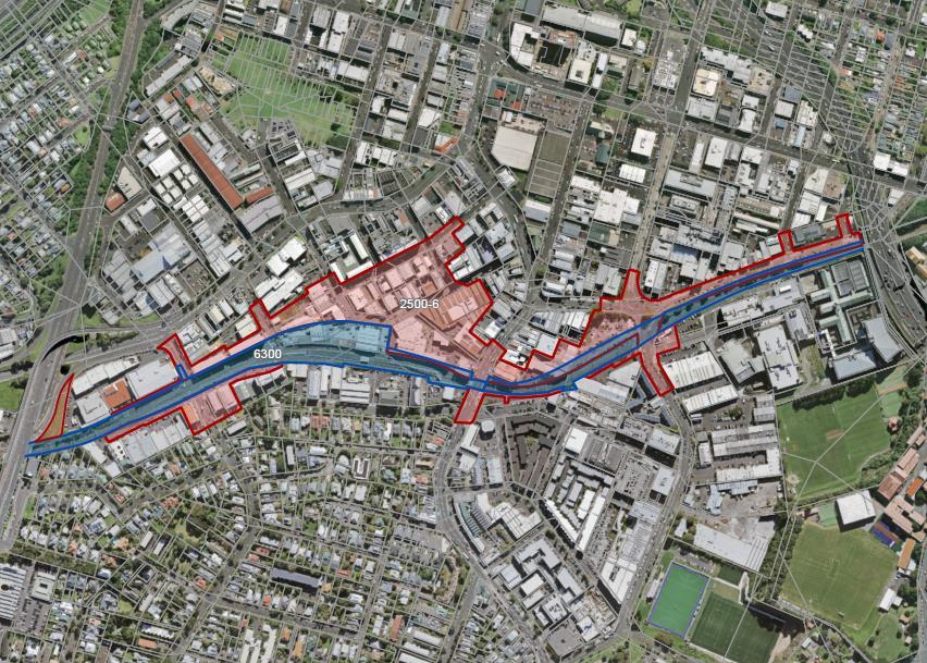
1 SSESCP-100 – Mt Eden CSA 4
Refer Drawings 390-100-RevA, 390-101-RevA
1.1 Scope of SSESCP
This SSESCP addresses the management of erosion and associated sediment discharges as a result of the works associated with the earthwork operations within the Mt Eden Station Area, specifically CSA4.
This SSESCP details the erosion and sediment control measures that have been implemented on site as a result of the enabling works and those measures that will be utilised up until the time that the primary Water Treatment Plant (WTP) has been commissioned.
It is anticipated that the primary WTP will be commissioned by January 2021.
The bulk earthworks are required to form what will become the rail trenches/cut and cover tunnels, which will also provide a ramp for the TBM to be manoeuvred into position. The excavation will encounter basalt, which is to be blasted in order to expediate the works and minimise the amount of rock-breaking required. In places, softer ground conditions are anticipated to be encountered, which may require the use of sheet piles
The work area covered by this SSESCP has a total area of approximately 37,500m2. Approximately 113,000m3 of material is to be cut from this area.
The existing site area is currently largely stabilised by the foundations of buildings and existing roads (specifically Shaddock Street). The foundations of the buildings will be retained until construction works require the removal of these foundations.
Entrance and exit to the site will be via Ngahura Street.
The proposed erosion and sediment control measures have been designed in accordance with the Auckland Council’s Guideline Document 2016/005 ‘Erosion and Sediment Control Guide for Land Disturbing Activities in the Auckland Region’ (GD05).
Earthworks associated with this ESCP:
➢ Construction of erosion and sediment controls;
➢ Excavation and removal of existing concrete foundations, driveways and parking areas;
➢ Cut to waste earthworks;
➢ Construction of tunnel support facilities.
1.2 Duration and Staging of Works
The bulk earthworks are programmed to commence in May 2020 and is programmed to take 26 weeks to complete.
The existing concrete and other impervious surfaces will be retained as long as practical.
The removal of these impervious areas will commence shortly after commencement of bulk earthworks.
1.3 Methodology / Erosion and Sediment Control Measures
Prior to the commencement of any earthworks the Construction Manager will inspect the site to confirm the suitability of the proposed controls and methodologies
A stabilised construction entrance will be formed to the work area from Ngahura Street.
A cattle grate will be installed on the site side of this access to allow for wheel washing as required.
Note, wheel washing is a contingency measure. The primary measure is to ensure vehicles remain on stabilised surfaces.
1.3.1 Cleanwater diversions
The existing kerb and channel on Ruru and Ngahura Streets are to be retained as cleanwater diversions. These will be enhanced (where required) as detailed in Appendix A to ensure capacity to divert runoff from the 50-year Rainfall Event.
Typically at this stage, all existing cesspits that are outside of the construction footprint will be retained as part of the cleanwater diversion network.
The existing kerb and channel, to the north of the future offices (11-13 Ruru Street and 6-10 Ngahura Street) will form cleanwater diversions.
At the lower end of Ngahura Street a trafficable bund will be formed across Ngahura to maximise the inlet capacity of the existing cesspits.
A section of the existing Nikau Street kerb (at the old intersection with Flower Street) is to be removed, this will be replaced with a hotmix bund. The remainder of the existing Nikau Street kerb and channel will direct runoff to the existing cesspits at the intersection of Nikau and Ruru Streets.
A further trafficable bund will be formed across Ruru Street to direct all cleanwater from Ruru Street also to the existing cesspits at the intersection of Nikau and Ruru Streets.
A hotmix bund will be installed along the wester side of the Flower Street diversion to divert cleanwater from this area.
This hotmix bund will extent across Shaddock Street to isolate the site from this cleanwater. This bund will follow the existing crest and will direct runoff to the existing cesspits in Shaddock Street east of the Flower Street intersection.
As part of the demolition of the buildings within 95 Mt Eden Road and 8 Shaddock Street, the lower sections of the perimeter walls will (where appropriate) be retained as cleanwater diversions.
Where this is not appropriate an aggregate bund, a minimum of 550mm high will be installed along this boundary.
This eastern diversion will discharge to the existing stormwater network within Shaddock Street.
The existing stormwater network along Shaddock Street will be retained until the permanent diversion has been installed. Note details of this diversion will be included in a subsequent SSESCP.
The kerb and channel along Mt Eden Road will be retained as a cleanwater diversion.
A 550mm high (minimum) bund will be installed along the boundary with the existing rail corridor. This bund will form both a cleanwater and a dirty water bund.
1.3.2 Dirty Water Diversions
The requirement for dirty water diversions on site is relatively limited as the majority of the site falls inwards towards the SRP (see section 1.3.3).
As noted above a 550mm high (minimum) bund will be installed along the boundary with the existing rail corridor. This bund will form both a cleanwater and a dirty water bund.
A sort section of dirty water diversion bund will be installed along the boundary between the future WTP and Shaddock Street.
1.3.3 Sediment Control
Existing stormwater inlets within the CSA4 area will be removed progressively by the excavation works. Prior to this they will either by blocked to prevent any ingress or will be protected in accordance with Auckland Council Best Practice: Catchpit Protection 2011. Note preference will be given to blocking these inlets and directing all runoff to SRP 1.
Sediment control on site will be provided primarily by SRP 1 constructed near the centre of the site.
SRP 1 receives surface runoff from a 2.75ha catchment area and will discharge to the existing stormwater network.
Runoff from the remaining 1.0ha area (typically in the area of the future Office and Parking Area) is currently a low point, and will continue to be so as works progress. Runoff from this area will be pumped to SRP 1 in accordance with Section 1.4.
In order to control runoff from the entire CSA4 area SRP 1 will be therefore sized to receive runoff from a 3.75ha catchment (see drawing 390-101-RevA).
Stage Specific Erosion and Sediment Control Plan (SSESCP)
SRP 1 will be Chemically Treated in accordance with the Flocculent Treatment Management Plan (FTMP) (see section 1.7).
Subject to the volumes of groundwater encountered, and the contaminants identified within the groundwater, a Water Treatment Plant may also be utilised either as a stand-alone device or as additional treatment before or after SRP 1, refer section 1.5.
1.4 SRP 1 Operation
1.4.1 Batch Dosing
In this method impounded flows are to be pumped to SRP 1 where it will be stored and batch dosed in accordance with the FTMP. In regard to this dosing (subject to confirmation) it is assumed (based on similar sites) that a dose rate of 4mg/L of Polyaluminium Chloride (PAC) will be appropriate. When the clarity has increased to greater than 100mm and the pH has been checked and confirmed to be within the range of 5.0 – 9.0 then the stored flows will be discharged as detailed in the procedures below.
The monitoring sheet for pumping activities is to be completed
Lift the floating decants above the maximum level to prevent a discharge during filling.
The pumped flows are to be discharged to the forebay to enter SRP 1 via the level spreader.
Pumping is to continue until complete or until SRP 1 has filled to the level of the primary spillway. Pumping is not to continue once this level has been reached.
Once pumping is complete the volume of stored water is to be noted and the correct volume of PAC added. The manhole riser appropriately marked to determine the actual volume of pumped storm water
The correct volume of PAC will depend on the optimum dose rate based on soil sample bench testing.
This PAC is to be added to the surface of the pond
The impounded water will then be mixed with the chemical using one of the following methods:
Mixing with a pole, paddle or oar
Mixing by circulating the impounded flows through a pump
Mixing by dragging semi-submerged floats through the surface area of the impounded water
SRP 1 is to then be left for approximately 2-3 hours until the discharge parameters are met.
Check and recorded the clarity and pH
In the event that the clarity is still less than 100mm and the pH is still within the range of 5.0 – 9.0 a 25% dose of the original dose of PAC is to be added and recorded.
SRP 1 is to than be left for approximately 2-3 hours
Check the clarity and pH again to see if the discharge parameters are met. This iterative process can be undertaken a maximum of 4 times, i.e. a maximum total additional dose of 100% of the original PAC volume is permitted. Following this the SRP, impoundment or DEB must be allowed to settle for 24 hours and the Environmental and Sustainability Manager notified.
In the event that after 24 hours the clarity of SRP1 is still less than 100mm, specialist advice is to be sought.
In the event that once the clarity of SRP1 is greater than 100mm, the pH is outside the limits of 5.0 – 9.0 then specialist advice is to be sought regarding correction of this pH. Once the clarity of SRP1 is greater than 100mm and the pH is within the range of 5.0 – 9.0, the SRP is to be discharged by releasing the decants. The time of this discharge and the pH and clarity are to be recorded on Monitoring Sheet for Pumping Activities.
1.4.2 Continuous Dosing
During Continuous Dosing the outlet of the pumps are again directed to the forebay of SRP1, however the outlet of the SRP is not plugged nor are the decants lifted. In this procedure PAC is continuously added to the inlet flows from the pump. In regard to this dosing (subject to confirmation) it is assumed (based on similar sites) that a dose rate of 4mg/L of Polyaluminium Chloride (PAC) will be appropriate. This is achieved by a 25 litre container of PAC discharging via a 13mm hose (standard reinforced garden hose) that is fitted with an orifice at the outlet directly
above the outlet of the pump. The 25 litre container is set 1m about the outlet to ensure the correct discharge rate which ‘drips’ directly onto the flows being discharged to the forebay.
3 potential pumps with a specific orifice size to achieve a dose rate of 5mg/L is shown in the table below. This data will be revised and will be specific to the optimum dose rates determined from bench testing for the relevant work area.
Figures in italics are preliminary and are to be confirmed before implementation
The procedure for continuous dosing is as follows:
The Monitoring Sheet for Pumping Activities sheet is to be completed
The appropriate pump is selected.
The outlet of the pump is to be secured within the SRP forebay.
The appropriate orifice is selected according to pump size.
The 25 litre container of PAC is to be placed 1m above the outlet point which is to be secured directly above (100200mm) the pump outlet.
The PAC is to be turned on.
The pump is to be started.
The PAC container is to be checked hourly to ensure sufficient volume remains
Each hour of pumping the clarity and pH is to be checked at the outlet.
In the event that the clarity falls below 100mm or the pH falls outside of the range of 5.0 – 9.0, pumping is to stop and the outlet plugged or decants lifted and dewatering continued as a batch dosed procedure.
1.5 Pumping through LAMELLA LT-50 (device to be confirmed)
In this option water is pumped through a portable water treatment unit(s), Lamella LT-50. The discharge from this may be directly to stormwater or to SRP1.
The Lamella LT-50 is a portable water treatment device. Sediment laden water is pumped into the LT-50, PAC (or other flocculant as determined by testing of soil samples during SRP construction) is added and the water is fed through ports into the Lamella plate packs. Clean water moves up through the plate packs and overflows through a discharge lauder and is discharged under gravity. Solids consolidate within the unit into a thickened sludge and are discharged automatically back onto site.
The LT-50 has the following features:
Automated PAC continuous dosing system
Automated continuous monitoring of pH and turbidity at the outlet
Text message alarm system triggered by pH and turbidity monitoring results
Automated texting of results from monitoring
The density of the sludge is monitored and discharged at regular intervals into a contained area on site.
50 m³/hr capacity
The procedure for operating the Lamella LT-50 is as follows:
Stage Specific Erosion and Sediment Control Plan (SSESCP)
The unit is started up and water is pumped into the LT-50.
Every fifteen minutes the turbidity and pH of the water is automatically monitored at the outlet and this data is sent to the Environmental and Sustainability Manager at these intervals. Each week the turbidity and pH data will be collated into a spread sheet which will be sent to the Auckland Council on a weekly basis.
If turbidity rises above 40 Nephelometric Turbidity Units (NTU) or the pH goes outside 5.0 – 9.0 a text message is automatically generated by the unit and sent to the Environmental and Sustainability Manager.
At all times at least one plant operator will be able to respond within 30 minutes of receiving the alert text message, this includes night time pumping.
In the event that the turbidity rises above 50 NTU or the pH falls outside the range 5.0 – 9.0 at the outlet the unit will be manually shut down. The water can then either be pumped to SRP1, by operating the valves at the tee intersection upstream or the water can be impounded within the work area
1.6 As-Built Certification
The required certification for the erosion and sediment control measures will be completed and submitted to the Team Leader Central Monitoring immediately following installation.
1.7 Chemical Treatment
SRP 1 will be chemically treated with rainfall activated devices in accordance with the Flocculant Treatment Management Plan.
The following table has assumed (based on similar sites) that a dose rate of 4mg/L of Polyaluminium Chloride (PAC) will be appropriate.
Figures in italics are preliminary and are to be confirmed before implementation
1.8 Contamination
Contamination investigations detailed in the Contamination Delivery Work Plan (C DWP) indicate low-level contamination within fill material and groundwater. The C DWP does not identify this area of work as requiring specific management in relation to erosion and sediment controls measures though testing to confirm compliance with the criteria for discharge is required as detailed in the Water Quality Discharge Monitoring Programme (WQDMP).
Stage Specific Erosion and Sediment Control Plan (SSESCP)
Appendix A – Erosion and sediment control calculations
Perimeter Bund Sizing Summary
11-13 Ruru Street and 6-10 Ngahura Street
Each of the existing kerbs have a maximum contributing catchment of 4,000m2 (note this ignores roof drainage within these catchments).
Conservatively it has been assumed that in a 50-year event (153mm/24hr HIRDS) the peak flow will be directed as a surface flow intercepted by the bund (note as above this ignores the roof catchment which is in the order of 75% of the total catchment).
This rainfall event results in a peak flow of 102L/s.
TP108
TP108 peak flowcalculations assuming a smallcatchment (Minimumtime-of-concentrationas specified by TP108)
Catchment
The existing kerb and channel are on a longitudinal grade, in the flatter sections of approximately 1.5%.
The existing kerb is approximately 150mm high, the carpark slope above the kerb is approximately 20%
A channel of the above dimensions will convey the 102L/s at a depth of approximately 140mm.
As a comparison if the roof catchment is removed the peak flow reduces to 25L/s which the kerbs will convey at a depth of 75mm.
Lower end of Ngahura Street
As above this area has a maximum contributing catchment of 5,000m2 (note this ignores roof drainage within this catchment).
Conservatively it has been assumed that in a 50-year event (153mm/24hr HIRDS) the peak flow will be directed as a surface flow intercepted by the bund (note as above this ignores the roof catchment which is in the order of 75% of the total catchment).
This rainfall event results in a peak flow of 127L/s.
The bund in this location, diverting runoff to the existing cesspits will have a longitudinal grade equal to the road crossfall, assumed to be 3%.
The bund will be a minimum of 400mm high and to be trafficable will have side slopes in the order of 33%, the existing road slope above the bund is approximately 10%
A channel of the above dimensions will convey the 127L/s at a depth of approximately 95mm. Nikau Street
The section of hotmix bund at the upper end of the Nikau Street diversion has a maximum contributing catchment of approximately 3,000m2 (note this ignores roof drainage within this catchment).
Conservatively it has been assumed that in a 50-year event (153mm/24hr HIRDS) the peak flow will be directed as a surface flow intercepted by the bund (note as above this ignores the roof catchment which is in the order of 75% of the total catchment).
This rainfall event results in a peak flow of 76L/s.
(10-minute
Impervious surfaces
Storage
Runoff/Rainfall
Pervious
Runoff/Rainfall
Combined Flow
Peak runoff fromsurfaces l/s 85.72
Peak outflow fromcatchment (allowing for lag) l/s 76.29
The bund in this location, diverting runoff to the existing cesspits will have a longitudinal grade of approximately 10%.
The bund will form a vee channel with the bund side slope of 1:1 and the upslope of 3-5% (1:20)
A channel of the above dimensions will convey the 76L/s at a depth of approximately 50mm.
The kerbed section of Nikau Street has a maximum contributing catchment of 1.7ha (note this ignores roof drainage within this catchment).
Conservatively it has been assumed that in a 5% AEP (108mm/hr HIRDS) the peak flow will be directed as a surface flow intercepted by the bund.
This rainfall event results in a peak flow of 432L/s.
TP108 peak flowcalculations assuming a smallcatchment (Minimumtime-of-concentrationas specified by TP108)
Catchment Area ha 1.7
Percentage of impervious cover 100%
Impervious SCSCurve Number 98
Pervious SCSCurve Number 86 24-hour rainfall mm 153
Peak outflow fromcatchment (allowing for lag) l/s 432.29
The existing kerb in this location has a grade of approximately 2% at the lower, flatter section of Nikau Street.
The existing kerb is approximately 150mm high, with the footpath behind providing a further potential channel depth of 100mm, the existing road slope above the kerb is approximately 3%
A channel of the above dimensions will convey the 432L/s at a depth of approximately 95mm.
To maintain a minimum 300mm freeboard and additional 150mm high hotmix bund will be placed at the rear of the existing footpath.
A further hotmix bund, a minimum of 400mm high will be installed across Ruru Street.
Flower Street
Stage Specific Erosion and Sediment Control Plan (SSESCP)
The Flower Street diversion has a maximum contributing catchment of approximately 3,000m2 (note this ignores roof drainage within this catchment).
Conservatively it has been assumed that in a 50-year event (153mm/24hr HIRDS) the peak flow will be directed as a surface flow intercepted by the bund (note as above this ignores the roof catchment which is in the order of 75% of the total catchment).
This rainfall event results in a peak flow of 76L/s.
The bund in this location, diverting runoff to the existing cesspits will have a longitudinal grade of approximately 15%.
The bund will form a vee channel with the bund side slope of 1:1 and the upslope of 3-5% (1:20)
A channel of the above dimensions will convey the 76L/s at a depth of approximately 35mm.
95 Mt Eden Road and 8 Shaddock Street
This diversion has a maximum contributing catchment of approximately 9,000m2 (note this ignores roof drainage
Conservatively it has been assumed that in a 50-year event (153mm/24hr HIRDS) the peak flow will be directed as a surface flow intercepted by the bund (note as above this ignores the roof catchment which is in the order of 75% of the total catchment).
This rainfall event results in a peak flow of 229L/s.
A channel of the above dimensions will convey the 229L/s at a depth of approximately 160mm.
Mt Eden Road
The section of Mt Eden Road where the existing kerb is to be retained has a maximum contributing catchment of approximately 4,000m2. This catchment is fully road surface and footpath and ignores existing road drainage.
The 50-year rainfall event in this catchment results in a peak flow of 102L/s.
TP108
The bund in this location, diverting runoff to the existing cesspits will have a longitudinal grade, in the flatter sections, of approximately 1.5%.
The bund will form a vee channel with the bund side slope of 1:1 and the upslope of approximately 10%
Peak
Impervious
Storage
Runoff/Rainfallat peak of rainfall 1.00
Peak runoff rate l/s
Pervious surfaces
Storage S mm 41.3
Runoff/Rainfallat peak of rainfall 0.87
Peak runoff rate l/s 0.00
Combined Flow
Peak runoff fromsurfaces l/s 114.29
Peak
The existing kerb in this location has a grade of approximately 2.5% at the lower, flatter section above the existing rail bridge.
The existing kerb is approximately 150mm high, with the footpath behind providing a further potential channel depth of 150mm, the existing road slope above the kerb is approximately 3%
A channel of the above dimensions will convey the 102L/s at a depth of approximately 55mm.
To maintain a minimum 300mm freeboard and additional 100mm high hotmix bund will be placed at the rear of the existing footpath.
SRP Sizing
SRP 1 will potentially control runoff from the full 3.75ha site.
in accordance with section F1.1.1 of GD05 this SRP, designed to the 3% criteria (300m3 (minimum) of storage for each 1ha of contributing catchment), would require 1,125m3 of storage.
Notwithstanding the above SRP1 is to be constructed as large as practical, initial design allows for 1,600m3
This additional storage and the manual operation of the pond will ensure that the deficiencies of compliant design, specifically the length to width ratio, will not adversely affect the performance of the SRP.
Due to the location of SRP 1 the installation of an emergency spillway is not practical. However the location of SRP1 means that any runoff in excess of the outlet capacity will pond on site. The 100 year rainfall event (172mm/24hr HIRDS) would result in approximately 6,450m3 of runoff. The site will be maintained to ensure that storage of at least this volume is maintained at all times.
Stage Specific Erosion and Sediment Control Plan (SSESCP)
Appendix B – Erosion and Sediment Control Drawings
Stage Specific Erosion and Sediment Control Plan (SSESCP)
Stage Specific Erosion and Sediment Control Plan (SSESCP)
Stage Specific Erosion and Sediment Control Plan (SSESCP)
2 SSESCP-200 – East Facing Connection 2 – Stage 1
Refer Drawings 390-200-RevA
2.1 Scope of SSESCP
This SSESCP addresses the management of erosion and associated sediment discharges as a result of the works associated with the earthwork operations within the East Facing Connection 2 (EFC2) area, specifically those works associated with stage 1 of these works.
Subsequent SSESCPs will be submitted for subsequent stages of work.
The works within the scope of this SSESCP, with particular regard to erosion and sediment, include:
• Setup of Construction Support Area 5 (CSA5),
• Construction of retaining walls, including diaphragm walls (D-Wall) and bored pile walls,
• Ground improvements, deep soil mixing (DSM),
• Bulk excavation
The work area covered by this SSESCP has a total area of approximately 13,000m2. Approximately 57,000m3 of material is to be cut from this area.
The existing site area is currently fully stabilised by the foundations of buildings, the NAL ballast and an existing metalled carpark area. The foundations of the buildings will be typically be retained as part of CSA5.
Entrance to the site will be via Water Street, the exit from the site will be to Normanby Road.
The proposed erosion and sediment control measures have been designed in accordance with the Auckland Council’s Guideline Document 2016/005 ‘Erosion and Sediment Control Guide for Land Disturbing Activities in the Auckland Region’ (GD05).
Earthworks associated with this ESCP:
➢ Construction of erosion and sediment controls,
➢ Excavation and removal of existing concrete foundations, driveways and parking areas,
➢ Piling,
➢ Deep Soil Mixing,
➢ Cut to waste earthworks.
Stage Specific Erosion and Sediment Control Plan (SSESCP)
2.1.1 Earthworks
Due to the site constraints it is impractical to load the excavated material directly into trucks for offsite disposal.
The excavated material will be loaded into site based trucks which will transfer the excavated material to the Muck Bin which is a bunded area where excavated material will be temporarily stockpiled to both allow it to drain (as appropriate) and to accumulate to volumes where efficient offsite disposal via truck and trailers can be undertaken.
Within this Muck Bin, internal bunds will isolate material that has been excavated from the D-Wall and or from within the Deep Soil Mixing where the runoff from these materials may affect the efficiency of the WTP (due to bentonite or cement).
The runoff from this material will be controlled (if necessary) by a separate WTP specifically designed and operated to control runoff from these activities (see ITA).
2.2 Duration and Staging of Works
The construction activities of Stage 1 are programmed to commence in May 2020 and will continue until December 2021.
For specific details of staging refer to the CEMP. Note as the sediment controls are designed to accommodate the full site area, the staging of works within the site perimeter does not effect the erosion and sediment control measures utilised.
2.3 Methodology / Erosion and Sediment Control Measures
As the overarching erosion and sediment control principle to be utilised in this area:
• Cleanwater will be diverted around the area of works,
• All surface water and ground water from within the work area will be collected and will be discharged via a Water Treatment Plant (WTP).
Prior to the commencement of any earthworks the Construction Manager will inspect the site to confirm the suitability of the proposed controls and methodologies.
A stabilised construction entrance will be formed to the work area from Water Street.
A stabilised construction exit will be formed at the outlet from the site to Normanby Road.
A cattle grate will be installed on the site side of this exit to allow for wheel washing as required. Any discharges from the wheel washing activity will be collected in a manhole and discharged via the WTP.
Note, wheel washing is a contingency measure. The primary measure is to ensure vehicles remain on stabilised surfaces.
Stage Specific Erosion and Sediment Control Plan (SSESCP)
2.3.1 Cleanwater diversions
The EFC2 area is typically bounded to the north by existing buildings and to the south by gardens and carparks on the southern boundary of the NAL.
Typically at this stage, all existing cesspits that are outside of the construction footprint will be retained as part of the cleanwater diversion network.
The NAL corridor forms a low point in the general topography of the area, through the length of the works this corridor has minimal longitudinal grade.
In order to isolate the EFC2 area from cleanwater flows from outside of the site, the existing kerb and channel and existing roof drainage will be utilised to divert runoff from the northern catchment. These will be enhanced (where required) as detailed in Appendix A to ensure capacity to divert runoff from the 50-year Rainfall Event.
The kerb and channel along Mt Eden Road will be retained as a cleanwater diversion.
This will be supplemented at the rear of the footpath with a low hotmix bund as required to provide 300mm freeboard.
The existing buildings 16-24 Mt Eden Road and 5-7 Water Street have a total area of approximately 3,000m2. Runoff from this area will be diverted by bunds within the site are and discharge to an existing catchpit at the rear of 24 Mt Eden Road and a new temporary catchpit within the site at the rear of 7 Water Street.
The runoff from the area between Water Street, Mt Eden Road, Boston Road and the EFC2 area will be directed to the existing catchpits at the lower end of Water Street, immediately onsite the site extent.
Cleanwater/dirty water diversion bunds will be installed along the EFC2 boundary to isolate the clean/dirty catchments in this location.
A 350mm trafficable bund will be included at the entrance to the site to isolate the clean/dirty catchments in this location.
The existing kerb and channel and footpath along Boston Road and Normanby Road are of sufficient height to divert runoff from the 50-year rainfall event without modification.
A 550mm high (minimum) bund will be installed along the boundary with the existing rail corridor. This bund will form both a cleanwater and a dirty water bund.
2.3.2 Dirty Water Diversions
The requirement for dirty water diversions on site is limited to diversion bunds along the eastern and southern extents of the work area.
As the works progress the required excavation will capture the majority of site runoff.
As noted above a 550mm high (minimum) bund will be installed along the boundary with the existing rail corridor. This bund will form both a cleanwater and a dirty water bund.
Stage Specific Erosion and Sediment Control Plan (SSESCP)
2.3.3 Sediment Control
As noted earlier the nature of the site precludes the ability to install a traditional sediment control device, specifically a sediment retention pond.
All water on site will be controlled via a Water Treatment Plant, that will discharge to the existing stormwater network.
2.4 Water Treatment Plan
The WTP at CSA 5 is located adjacent to the entrance off Water Street. This plant will control water from the earthwork activities within the EFC2 area.
Once the primary WTP within SCA4 is commissioned, discharges from the EFC2 area may also be pumped to this WTP. This would allow the decommissioning of this WTP, a revision to this SSESCP will be prepared detailing that change.
The earthworks area that will be controlled by the EFC2 WTP is approximately 0.75ha in area (this area excludes the ITA areas).
The earthworks in this area include:
• Traditional cut to waste,
• Bored piling operations
• D-Wall construction
• Ground improvement, deep soil mixing with cement
• Trenching for service installations
In this area, discharges from the D-Wall activities will be isolated and kept separate from the general site runoff.
The undertaking of the ground improvements in this area will elevate the pH of discharges in this area. This will be monitored as part of the WTP operation and will be balanced, as required through acid injection.
The soils in this area that have been encountered to date are typically silty clays, as the depth of the excavation increases it is expected these soils will progress through Tauranga Group alluvium, clayey to sandy silts. These soils have been considered in the design of the WTP.
The volume of water to be controlled needs to be considered in the design of the WTP.
The EFC2 area (0.75ha) is expected to generate approximately 3.5m3/hr of groundwater.
The 61mm (see ESCP section 4.1.2.1.2) daily rainfall event will generate a further 458m3, per day (19m3/hr).
The combination of the above results in a requirement to be able to control 22.5m3/hr (540m3 per day).
Stage Specific Erosion and Sediment
Control Plan (SSESCP)
The selected WTP is a Silt Buster HB-50 lamella clarifier. This WTP will include:
9m3 settling skip bin
Submersible pump with float switch
Dosing Units x 3 (pH, Flocculent, coagulant) & hoses
1 x HB50 Siltbuster®
1 x 5,000ltr water tank (recycling of clarified water)
2x 1000L IBCs for sludge collection
The HB50 Siltbuster® has a rated treatment capacity of 50m3/hr (1,200m3 per day). This capacity means that additional storage is only required for the 1% AEP rainfall event. This additional storage will be provided on site.
The additional storage required for various storm events is as follows:
2.5
Operation of HB50 Siltbuster®
The HB50 Siltbuster® will be operated in accordance with the attached operation procedure.
2.6 As-Built Certification
The required certification for the erosion and sediment control measures will be completed and submitted to the Team Leader Central Monitoring immediately following installation.
2.7
Chemical Treatment
The HB50 Siltbuster® will be chemically treated in accordance with the FTMP.
Stage Specific Erosion and Sediment Control Plan (SSESCP)
2.8 Contamination
Contamination investigations detailed in the Contamination Delivery Work Plan (C DWP) indicate low-level contamination within fill material and groundwater. The C DWP does not identify this area of work as requiring specific management in relation to erosion and sediment controls measures though testing to confirm compliance with the criteria for discharge is required as detailed in the Water Quality Discharge Monitoring Programme (WQDMP).
Stage Specific Erosion and Sediment Control Plan (SSESCP)
Appendix A – Erosion and sediment control calculations
Perimeter Bund Sizing Summary
Mt Eden Road
The section of Mt Eden Road where the existing kerb is to be retained as a cleanwater diversion has a maximum contributing catchment of approximately 1,000m2. This catchment is fully road surface and footpath and ignores existing road drainage.
The 50-year rainfall event in this catchment results in a peak flow of 25L/s.
TP108 peak flowcalculations assuming a smallcatchment
(Minimumtime-of-concentrationas specified by TP108)
The existing kerb in this location has a grade of approximately 2.5% at the lower, flatter section above the existing rail bridge.
The existing kerb is approximately 150mm high, with the footpath behind providing a further potential channel depth of 150mm, the existing road slope above the kerb is approximately 3%
A channel of the above dimensions will convey the 25L/s at a depth of approximately 30mm.
To maintain a minimum 300mm freeboard and additional 100mm high hotmix bund will be placed at the rear of the existing footpath.
16-24 Mt Eden Road and 5-7 Water Street
Each of the existing kerbs have a maximum contributing
of 1,500m2 (note this ignores the existing drainage).
Stage Specific Erosion and Sediment Control Plan (SSESCP)
Conservatively it has been assumed that in a 50-year event (153mm/24hr HIRDS) the peak flow will be directed as a surface flow intercepted by the bund (note as above this ignores the roof catchment which is in the order of 75% of the total catchment).
This rainfall event results in a peak flow of 38L/s.
TP108 peak flowcalculations assuming a smallcatchment (Minimumtime-of-concentrationas specified by TP108)
The bunds along these boundaries will have a longitudinal grade, in the flatter sections of approximately 2.0%.
The bund will form a vee channel with the bund side slope of 1:1 and the upslope of 3-5% (1:20)
A channel of the above dimensions will convey the 38L/s at a depth of approximately 40mm.
Water Street
The section of bund to be constructed at the lower end of Water Street has a maximum contributing catchment of approximately 2,500m2 (note this ignores roof drainage within this catchment).
Conservatively it has been assumed that in a 50-year event (153mm/24hr HIRDS) the peak flow will be directed as a surface flow intercepted by the bund (note as above this ignores the roof catchment which is in the order of 75% of the total catchment).
This rainfall event results in a peak flow of 64L/s.
Stage Specific Erosion and Sediment Control Plan (SSESCP)
TP108 peak flowcalculations assuming a smallcatchment (Minimum
as specified by TP108)
The existing kerb is approximately 100mm high, with the footpath behind providing a further potential channel depth of 150mm, the existing road slope above the kerb is approximately 3%
A channel of the above dimensions will convey the 64L/s at a depth of approximately 45mm.
To maintain a minimum 300mm freeboard and additional 100mm high hotmix bund (minimum) will be placed at the rear of the existing footpath.
It is to be noted that the EFC2 area falls away from this bund.
12 Boston Road
The bund between 12 Boston Road and the EFC2 area has a maximum contributing catchment of approximately 1,000m2
The 50-year rainfall event in this catchment results in a peak flow of 25L/s.
Stage Specific Erosion and Sediment Control Plan (SSESCP)
TP108 peak flowcalculations assuming a smallcatchment
(Minimumtime-of-concentrationas specified by TP108)
The lower portion of this diversion is already formed by a retaining wall (retaining the site area).
To isolate the clean and dirty areas a 350mm high (minimum) bund will be installed along this boundary.
It is to be noted that the EFC2 area falls away from this bund.
Boston Road and Normanby Road
The section of Boston and Normanby Roads where the existing kerb is to be retained as a cleanwater diversion has a maximum contributing catchment of approximately 2,000m2. This catchment is fully road surface and footpath and ignores existing road drainage.
The 50-year rainfall event in this catchment results in a peak flow of 51L/s.
Stage Specific Erosion and Sediment Control Plan (SSESCP)
TP108 peak flowcalculations assuming a smallcatchment (Minimumtime-of-concentrationas specified by TP108)
The existing kerb in this location has a grade of approximately 3% at the lower, flatter section above the existing rail bridge.
The existing kerb is approximately 150mm high, with the footpath behind providing a further potential channel depth of 200mm, the existing road slope above the kerb is approximately 3%
A channel of the above dimensions will convey the 51L/s at a depth of approximately 40mm.
The existing kerb height and footpath height are therefore sufficient to provide 300mm freeboard for the 50-year event without modification.
Stage Specific Erosion and Sediment Control Plan (SSESCP)
Appendix B – Erosion and Sediment Control Drawings
Stage Specific Erosion and Sediment Control Plan (SSESCP)
Appendix C – Operation of HB50 Siltbuster®
Standard Operating Procedure
HB 50
Standard Operating Procedure
Technical Services
Siltbuster (HB50 Hopper Bottom)
Standard Operating Procedure
HB 50
Table of Contents:
1. Overview.
1.1 Principal Conponent and features – Siltbuster HB50
1.2 Performance.
2. Establishment.
2.1 Lifting and Handling.
2.2 Dimensions.
3. Operation.
3.1 Personal Protective Equipment
3.2 Training.
4. Emptying of Siltbuster (Desludging)
5. General Maintenance.
6. Trouble Shooting.
Standard Operating Procedure
HB 50
1. Overview.
The Siltbuster HB50 units are highly effective mobile lamella clarifiers and have been specifically designed to provide water clarification for a range of applications. Process water, groundwater or site run-off can be treated either for re-use or discharge off site either to watercourse or sewer. The units are ideal for removing free phase oil from water being discharged to sewer or river. The 50 of HB50 refers to the 50 Square meters of plates inside the unit.
All our units are “Registered Designs”, Patented or have Patents Pending. Safety Systems that apply to this Standard Operating Procedure (SOP) are put in place for the safety of the operator, the public, and workers.
Standard Operating Procedure
HB 50
1.1 Principal Components & Features - Siltbuster HB50
All tank components are fabricated from Mild Steel.
The unit will be painted to the following spec: External surfaces – abrasive blast to Class 2.5, painted in a Jotacoat 605 two pack epoxy to 250Nm with a Top Coat hardtop ultra pack "Polyurethane" to 50pm, colour G11, bottle green.
Water Inlet
Water Outlet
SludgeDischarge Valves
WaterDrain-Down Valve
(fig 1.1)
Internal Surfaces - abrasive blast to Class 2.5, painted 2 pack epoxy coating reinforced with glass flakes to 500pm, colour N52 Mid Grey.
Main Clarifier Unit
SludgeHoppers
Standard Operating Procedure
HB 50
1.2 Performance
The Siltbuster HB50 has a maximum recommended hydraulic capacity of 50m3/hr (14litres/sec).
The performance of the unit is material specific and the Siltbuster 50 Series is nominally designed to achieve 90% removal of the +15 micron diameter particles (medium sized silt) at a flow rate of 45m3/hr, +10micron at 20m3/hr and some +6 micron at 5m3/hr. Under normal operating conditions the unit will also remove a significant proportion of the material in the 2 to 15pm (fine to medium sized silt) range. These are based on average particle densities.
The Siltbuster will not typically remove very fine particles such as very fine silt or clay without chemical additives. The unit will also not remove colour from water.
The volume of water which can be processed by the unit is dependent upon the nature of the liquid/solid mix to be processed. The graph below (fig 7.1) provides only a general performance guide. The hydraulic capacity is 50m3/hour.
NB: Additional chemical dosing maybe required to enhance the operation of the Siltbuster.
Standard Operating Procedure
HB 50
2. Establishment
The Siltbuster HB50 should be located in a position where:
• The groundisfirm enough to support the flooded weight of the unit (approx. 10 tonnes).
• The ground is reasonably level. The top edge of the unit should be placed level to within 10mm.
• Due to the weight of the unit permanent anchoring is not required. However if this option is required then either holes can be drilled into the skids or straps constructed and placed over the skids in each corner and bolted to the ground.
• Sufficient clearance overhead is required to allow for the periodic removal of individual lamella plates.
• Safe access to the unit is available for routine inspection and maintenance.
• There is no likelihood of the site eroding during heavy rain or runoff.
• Adequate security can be provided from unauthorised access.
• Removal of sludge can be carried out safely and without risk of polluting site.
Note:
1. Ladders provided on Siltbuster units are for the purpose of climbing to carry out visual inspection only while maintaining a three point grip and are not intended for carrying out tasks.
2. The purchaser/hirer is responsible for assessing the site and determining prevailing hazards or risks. Advice offered in this brochure only highlights some common hazards and risks and is not intended as a complete checklist.
3. The purchaser/hirer is responsible for identifying hazardous or toxic products contained within the materials processed through the units and must develop safety control measures for staff and others who may be affected.
4. If placing units in elevated position hirer/purchaser should consider distance from ground surface to top of unit in regards to relative state regulations on working at heights.
The Siltbuster unit itself requires no power, has no filters or moving parts. As a result, apart from emptying as required, the unit is virtually maintenance free.
Standard Operating Procedure
HB 50
2.1 Lifting and Handling
The Siltbuster HB50 unit incorporates four lifting eyes, one located at each of the upper corners of the unit for lifting with chains, straps etc. Fork Lift channels are also provided at the base of the unit to enable lifting by a fork lift/JCB with fork attachment.
WARNING:
The unit should NOT be lifted or moved by attaching lifting equipment to any other part of the unit as this may result in damage to the unit or cause personal injury.
The unit should only be lifted WHEN EMPTIED OF WATER AND SOLIDS.
The sludge valves should be in the “OPEN POSITION” whilst been transported.
Standard Operating Procedure
HB 50
The Siltbuster unit has lifting eyes located at the upper corners of each unit.
When shifting units with a forklift select a forklift with suitable capacity to lift the unit (suitable Working Load Limit to suit the load at the center) and capable of traversing the site safely.
Consider height of the load when travellingandidentifyhazardsandrisks on site and along your travel route.
Standard Operating Procedure
2.2 Dimensions
Size – overall dimensions:
Width - 1700mm
Length - 3700mm (3900mm with inlet fittings attached)
Height - 3100 overall (with lifting eyes)
Weight - 2500kg (empty but with all plates and fittings).Weight full (wet) 9,000kg approx.
CentreofGravity – The units center of gravity is the middle point between the four lifting points.
Standard Operating Procedure
HB 50
3. Operation (Manual Mode)
a. Check submersible pump (or sump pump) is not sitting in the sludge/silt within the sump. If it is, raise the pump, so the suction head is no longer in the silt. NB: this is probably the key step in making the Siltbuster operate at its best effectiveness and efficiency.
b. Connect the discharge hose from the sump pump to the inlet connection of the Siltbuster.
c. Connect the discharge hose to the outlet end of the Siltbuster, and run the hose to the discharge point from the site – this will likely be either, a trade waste connection, a stormwater connection, or a tank. Only discharge water to an approved or consented outlet.
d. Ensure hopper valves are closed.
e. Start the sump/submersible pump.
f. Check water is flowing into the Siltbuster, and there are no leaks from the hoses.
g. Check water is flowing out of the Siltbuster, and not accumulating in the main body of the unit itself. If the water level is rising, then the sump pump is delivering too much volume. Close/throttle pump back to match the incoming and outgoing flowrates.
h. Check the discharge water quality – this will be site specific, and will be dependent on the discharge consent conditions.
i. During initial operations, periodic checks should be made to determine whether or not sludge needs to be removed from the hoppers of the Siltbuster. The frequency of sludge removal will vary, dependent on the solids/silt load coming into the Siltbuster, and the flowrate which is being introduced.
j. If the quality of the discharge water deteriorates (i.e get dirtier) over time, this is an indication that sludge has built up in the hopper, and needs to be removed. If the discharge water becomes extremely dirty very quickly, this would suggest the hoppers are full of sludge, and needs to be removed immediately. (Sludge levels can be checked via the test ports on the Siltbuster cones)
k. Refer to Section 4 – Sludge Removal, for how to remove sludge from the hoppers.
l. Periodically, drain the Siltbuster fully, and hose down the plates and hoppers. The frequency will be determined by the build-up of sludge seen on the lamella plates.
3.1 Personal Protective Equipment
The use of Personal Protective Equipment (PPE) is an important part of ensuring workers aren’t injured.
The manager shall provide workers with the appropriate personal protective equipment (PPE) before beginning their duties.
Standard Operating Procedure
HB 50
ACTION POINT: All workers must wear issued PPE.
Workers shall maintain their PPE in good condition and contact their manager if they require replacement or additional PPE. Workers can request additional PPE which may be issued at the manager/supervisor's discretion.
The PPE required to perform this task includes:
3.2 Training
Workers who are trained and assessed as competent are better equipped to perform the tasks required in this SOP and to perform them safely.
The manager must ensure staff are adequately trained in the operation of the Siltbuster unit. This includes a competency assessment on the Siltbuster operation, and an understanding of this SOP. This training, and assessment will be acknowledged on a formal training record.
Workers must also be trained in any checklists or maintenance procedures associated with this equipment.
MORE INFORMATION:
Please refer to the Manufacturers operating manual.
ACTION POINT
Workers must read and understand this procedure before undertaking any duties associated with this SOP.
Standard Operating Procedure
HB 50
Workers must follow all of the requirements within this SOP at all times.
Where it becomes difficult to follow the requirements of this SOP, workers must immediately report to the manager.
Workers must ensure the safety of themselves and others whilst at work and report all incidents, hazards, near hits and injuries on an Incident Form.
4. Desludging
The frequency of emptying the Siltbuster HB50 unit is dependent on the solids loading and the nature of the solids. Larger grain sizes (sands to gravel’s) do not generally flow as easily as finer sizes (silts) and tend to need more frequent cleaning to prevent hanging up in
Typical emptying frequencies vary from daily to fortnightly and we suggest you empty “little and often” until you know the material you are dealing with and how long you can leave the sludge in the unit whilst ensuring it is still fluid and flowable.
If solids have become solidified (“set”) then the small 1” ball valves (“sparge”) allow water or air to be injected back into the hopper under pressure to re-agitate (fluidised) the solids.
1” Sparge ball valves c/w Minsup fittings
Standard Operating Procedure
HB 50
Removal of sludge via the Discharge Valves can be made back to a site settling pit or to storage for removal later ie IBC’s or larger tanks.
5. General Maintenance
Notes:
1. The visual inspection should include inspection of the water surface for floating material (leaves etc).
2. Emptying: see previous instructions. (Section 4)
3. Some materials (especially charged particles) can adhere to the PVC plates and these will need periodic cleaning. The unit should be allowed to settle overnight, drained with the PVC sheets pressure washed in-place as it drains to avoid silt drying in place.
All frequencies given depend on the usage of the equipment and are given as typical guides.
Standard Operating Procedure
HB 50
6. Trouble Shooting
The Siltbuster HB50 itself requires no power, has no filters or moving parts and apart from emptying, the unit is virtually maintenance free.
As the nature of dirty water to be treated varies in terms of quantity and solids content, the table below lists some problems that could arise along with the actions required to solve the problems.
SYMPTOM
Water is overflowing from the inlet chamber or part way along main tank
REMEDY
Typical Causes:
1. Too much flow through unit (unit overloaded) 1. Reduce flow through the unit
2. Sludge in contact with plates 2. Unit needs emptying of sludge
Water discharge is dirty
Typical Causes:
1. Too much flow through unit (unit overloaded) 1. Reduce flow through the unit 2. Add multiple units in parallel 2. Water contains very fine silt and clay particles 3. Chemical conditioning of inflow required.
In any other cases contact EnviroWaste Technical Services 09 636 0350
Appendix C: Flocculant Treatment Management Plan
Appendix D: Consultation Record
D1 CLG Comments
A CLG was held via Microsoft Teams on 11 May 2020 and no specific concerns relating to erosion and sediment control were raised.
D2 IPR Comments
No specific comments relating to Erosion and Sediment Control Plan were raised.
D3 Auckland Council Comments
No specific comments relating to Erosion and Sediment Control Plan were raised.
D4 Mana Whenua
The ESCP was issued to Mana Whenua in May 2020 for review.