STRUT-BASED FUNICULAR STRUCTURES
Spatial Concrete Column
Columns, Topology, Volume, Load Path
Saltatur: Composite Funicular Structure For Reassembly
Hedracrete: Self-Supporting Funicular Branching Concrete
Compression-Only Floors Spanning Columns
Prototyping 3D-Printed Compression-Dominant Funicular
Floors Using Scaled Fabrication Models
Litekit House with Prefab Structure
Designing Airplane Wing Structures Using 2D Funicular Networks SUMMARY
FACE-BASED FUNICULAR STRUCTURES
Hollow Glass Unit Bridge; Vitrum Leve
Multi-Layer Sheet-Based Lightweight Funicular Structures
Shellular Structures and Applications in Micro- and Macro-
Scale Systems
Shellular Polyhedral Materials
Bio-Based Composite Spatial Shell Structures
Biomaterial Composite Design and Shellular Structures
Development for Augmented Earthen Construction
Self-Healing of Fractured Shellular Metal Structures
Origami and Polyhedral Systems
HYBRID FUNICULAR SYSTEMS
Diamanti: 3D-Printed, Post-Tensioned Concrete Canopy
3D-Printed Carbon-Absorbing High-Performance Building
Structure
Design Innovation
Prototyping
Application of Graphic Statics and Strut-and-Tie Models in Designing Innovative Timber Structures
Multi-Material 3D-Printing
Dove Wave
THE GENERATIVE POWER OF RECIPROCAL POLYHEDRONS
Future Airport Structure Typologies
Mass Timber Studio Florrisant Fossil Beds National Park Lightweight Timber Structure
BIBLIOGRAPHY
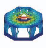
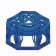
EXPERIMENTAL RESULTS
The average 28-day compressive strength of concrete is 46 MPa (6,630 psi). The second modulus of elasticity specified by ACI Committee 363R-10 is used to calculate the modulus of elasticity of the concrete. Comparison between the potentiometer measurements indicated a slight difference between the left and right sides of the sample; 0.5 mm (0.02”) was recorded as the maximum gap between the two potentiometers.
This means the top loading plate was not completely level during the test and experienced a 0.08% slope. This caused the sample to undergo slight non-uniform compression. As can be derived from the different stages of sample failure, one of the members popped out after reaching its maximum buckling load, causing local failure. The sample failed suddenly in a simultaneous explosive collapse of all core members subject to maximum load.
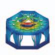
In the design process of GS, external loads at each support are considered unit loads. Based on the external loads, the force in each member can be calculated using a GS model. Further, the size of the members is associated with the number of internal forces, meaning the areas of the faces in the force diagram. For validating the amount of internal forces in the PGS design process and the physical test, the ultimate load carried by the sample in the test served as a basis. The ultimate load of 216 kN (48.69 kips) was chosen for the comparison between the test results and the analytical model, and internal forces were collected from both the physical and analytical models in relation to these loads.
In the members subject to axial compression forces, the experimental results predict the PGS load within a 5% error margin. The test results show that the ratio of the internal force measured in a member of the sample according to the total applied load in the test is equal to the ratio of the internal force according to the applied load in PGS. This means the distribution of internal forces measured in the test can be accurately predicted by PGS.
Moreover, the experimental results reveal that local bucking and failure do not immediately cause the global failure of the system due to the indeterminacy of the funicular geometry. The efficiency of the spatial funicular system is also verified by all sample members simultaneously collapsing under their maximum strength.
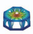
BROADER APPLICATIONS
The conclusion of this experiment is that the structures designed using PGS and dimensioned based on the magnitude of internal forces given by this method are among the most efficient of systems. This conclusion is based on comparing the self-weight versus the total load-bearing capacity of the concrete. Thus, a small exercise opens the door to various designs and experiments of architectural structures on large scales. Here, the reduction of construction materials does not compromise the structural behavior of the system. Nevertheless, the performative criteria of each design and system should be developed with respect to the objectives of each project, and these criteria certainly differ from one project to the next.
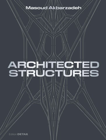
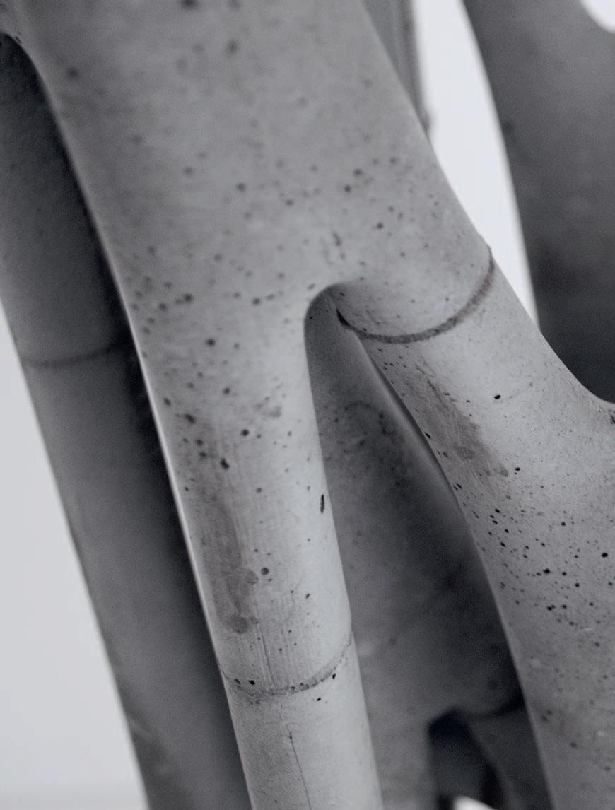
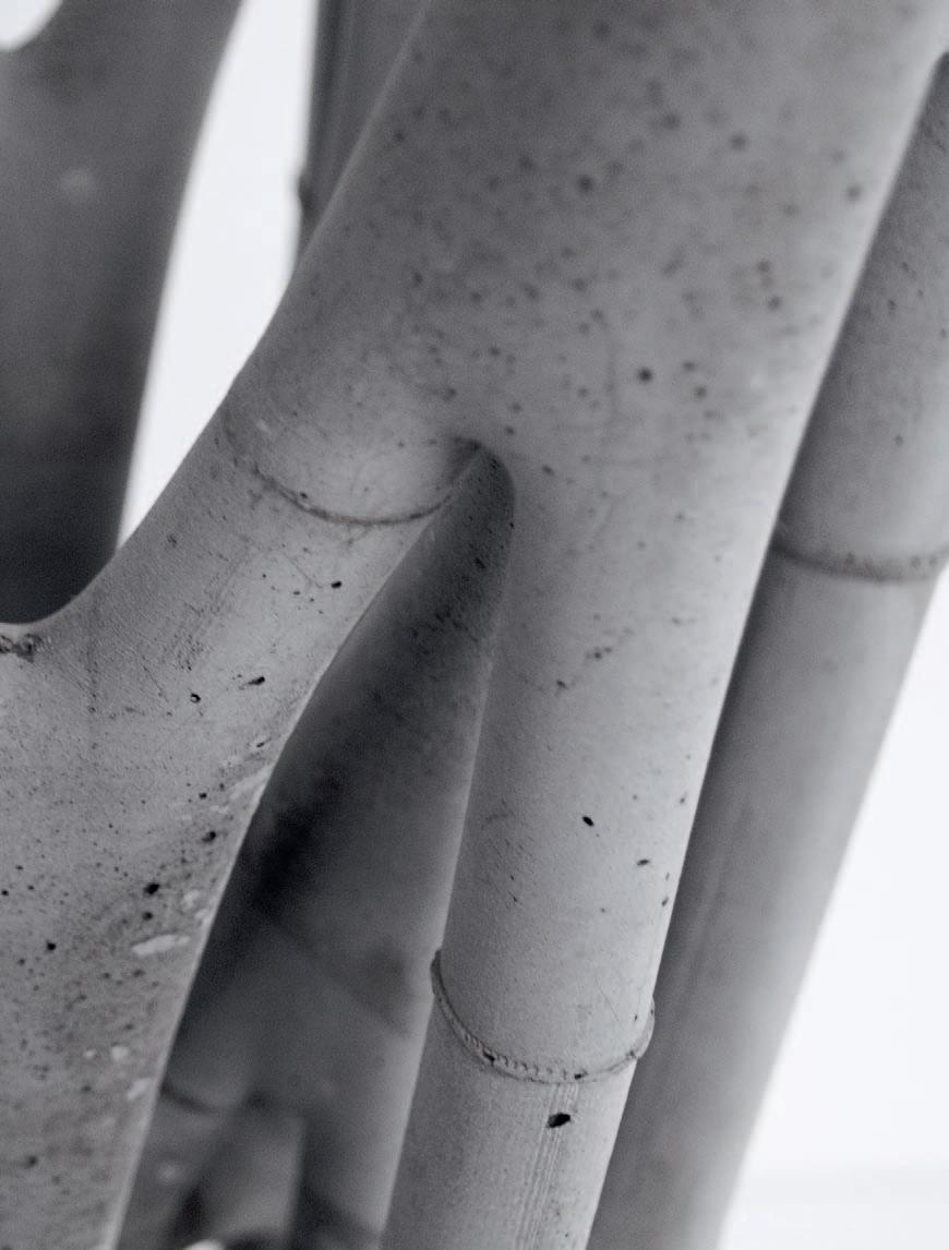
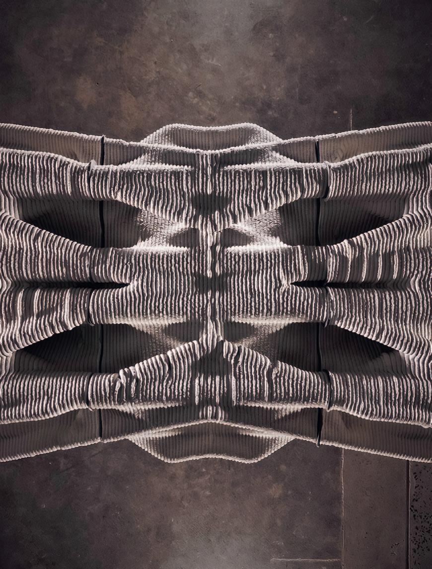
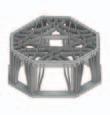
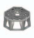
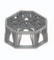
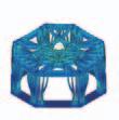
1.1.15: The front view of the 60 cm sample.
1.1.16: The total load-bearing capacity is approximately equivalent to the weight of four Asian elephants stacked on top of the structure.
Displacement (mm)
1.1.17: The load-displacement curve.
Fig1117: Theloaddisplacementcurve
Fig.
Fig.
Fig.
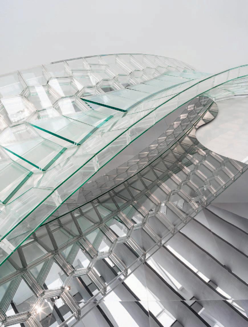
Fig. 2.1.1: Completed 10 m bridge. Photo credit: Corning Museum of Glass.
Masoud Akbarzadeh, Yao Lu, Joseph Yost, Damon Bolhassani, Jens Schneider
2.1 HOLLOW
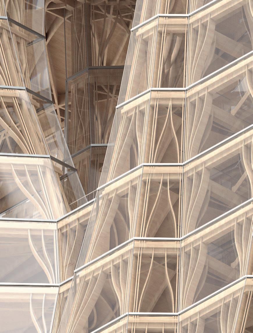
Glass is commonly used in building construction for windows, skylights, and curtain wall facades, where it typically does not serve as a primary structural material. As a result, it is often perceived as fragile, unsafe, and unsuitable for structural applications. However, when properly designed and engineered, glass can demonstrate remarkable structural performance, offering the potential to unify both architectural and structural functions within a single material. This research series proposes a modular all-glass structural system using a hollow glass unit (HGU) as a construction module (Figure 2.1.2 and 2.1.6, p. 122) and presents structural design projects built with this novel system.
Using PGS in structural form finding results in lightweight structures with high-performance structural behavior.60, 68 The resulting structural forms are polyhedral geometries with planar faces. Therefore, not only does PGS lead to efficient structural forms, but its planarity constraint facilitates construction with flat sheet materials (Figure 2.1.4). To take advantage of the planar geometry of the reciprocal polyhedral diagrams in construction, this research will explore the structural efficiency and behavior of a lightweight, ultra-transparent glass pedestrian bridge made of planar glass sheets in compression.
The final design of the bridge features a 10 m (32.81 ft) span supported by two metal abutments, with a 1 m wide glass deck for pedestrian traffic (Figure 2.1.1) . Its asymmetric geometry enhances performance under both asymmetric and lateral loading conditions. The structure of the bridge is composed of hollow, three-dimensional polyhedral glass blocks with planar faces, bonded together using a transparent structural acrylic adhesive.
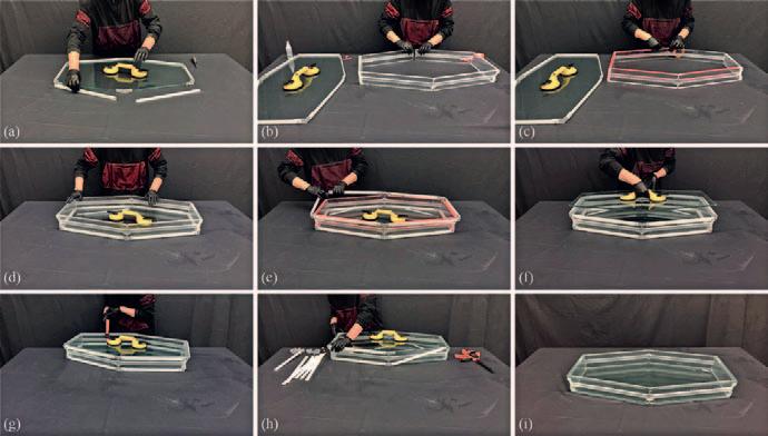
Both CNC milling and 5-axis waterjet cutting provide good fabrication accuracy for the individual parts. Subsequently, jigs and bars are developed to facilitate the assembly of each HGU and to position the parts before permanently bonding them with VHB tape. The jigs are 3D-printed with polylactic acid (PLA), and the bars are CNC-cut from 6 mm high-density polyethylene (HDPE) sheets. The jigs and bars work together as hoops, which confine the angles of the individual parts and the overall dimensions of the HGU. The assembly of a typical HGU is illustrated in Figure 2.1.16.
To strengthen the bonding of the VHB tape, clamps are used to apply a recommended pressure of about 100 kPa (Figure 2.1.16g). Lastly, all PLA jigs and HDPE bars are removed (Figure 2.1.16h), thereby completing the assembly of one HGU (Figure 2.1.16i).
Fig. 2.1.16: The assembly of a typical HGU: (a) the bottom deck plate and the bottom hoop of PLA jigs and HDPE bars; (b) all lateral plates are connected into a side-wall loop; (c) apply VHB tape to the bottom of the side-wall loop; (d) bond the side-wall loop to the bottom deck plate; (e) apply VHB tape to the top of the side-wall loop and place the top hoop of PLA jigs and HDPE bars; (f) place the top deck plate into the hoop; (g) strengthen the VHB bonding using a clamp; (h) remove all PLA jigs and HDPE bars; (i) a completed HGU.
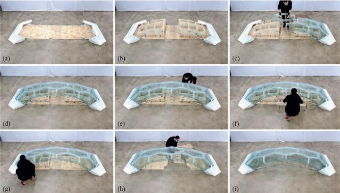
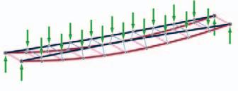
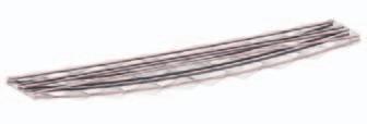
The assembly of the entire bridge begins after the assembly of all 13 HGU is completed. For this purpose, CNC-cut plywood panels are placed on the floor in order to precisely set the two steel abutments. Next, the two steel abutments are placed on the floor and attached to the plywood panels with shims underneath them for leveling purposes. After the locations of the steel abutments are precisely determined, two tension ties are connected to the abutments and tightened for purposes of stability. The tension ties are also key structural elements: they counteract the thrusts created by the HGU and ensure a compression-dominant state within the bridge.
The height-adjustable falsework is then placed on the plywood panels (Figure 2.1.17b). This falsework consists of plywood waffle structures and leveling feet that feature an adjustable range of 7 cm. It is designed as two separate parts, each having three layers for easy disassembly and removal from below the bridge after the assembly is complete. The Surlyn sheets are later placed on the steel abutments to avoid steel-to-glass contact. For other Surlyn sheets between the HGU,
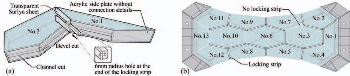
one side of each sheet is glued to the corresponding HGU to fix its position using Gorilla™ transparent spray adhesive, which provides strong bonds without adding intolerable construction error. The choice of the assembly sequence of the HGU has a large impact on the number and locations of butterfly locking connections. It is also critical to note that the final keystone HGU may not have any butterfly locking mechanism on its lateral plates. Hence, it is more vulnerable to sliding and rotation. For this reason, a unit directly supported by the steel abutment with four sides is selected as the keystone (Figure 2.1.18b, unit No. 13).
The final assembly sequence aims at limiting the number of lateral plate pairs that cannot have butterfly connections. Eventually, 20 out of the total 26 HGU-to-HGU contacts are secured by the butterfly locking mechanisms. Construction errors are almost inevitable at such scales, and it is impossible to know how errors will build up in advance. The distance between the two steel abutments can be adjusted by a turnbuckle to mitigate some errors in the glass bridge assembly. Also, the ductility of the Surlyn sheets absorbs a certain level of errors.
Fig. 2.1.17: (a) Use plywood panels to locate the steel abutments; (b) place the falsework on the plywood panels; (c) to (d) set HGU on the falsework; (e) turn the leveling feet and lower the falsework; (f) remove the middle layer of the falsework; (g) remove the other parts of the falsework; (h) remove the plywood panels; (i) a completed glass bridge.
Fig. 2.1.18: (a) Typical connection between two HGU. (b) Assembly sequence and corresponding
Maximilian E. Ororbia, Hua Chai, Yefan Zhi, Karolina Pajak, Damon Bolhassani, Paul Kassabian, Mathias Bernhard, Masoud Akbarzadeh
3.1 DIAMANTI: 3D-PRINTED, POSTTENSIONED CONCRETE CANOPY
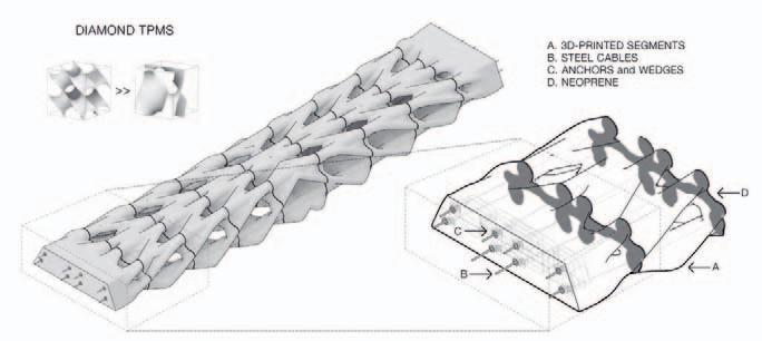
Authors p. 209). The segments are post-tensioned by eight ungrouted steel cables. Beneficially, the prefabricated modular, ungrouted assembly allows for the structure to be disassembled at the end of its service life, readily separating concrete and steel construction materials for recycling purposes, as is also the case after structural testing. Overall, the design and fabrication approaches developed in this work include multiple intertwined innovative strategies resulting in highly efficient structural systems. The amount of construction materials needed compared to conventional structural systems was reduced by utilizing 3D-printed concrete and post-tensioning. In general, the prefabrication strategy yields faster erection times, reduces soft construction costs, eliminates the need for formwork, allows for recyclability, and minimizes the overall carbon emissions of concrete construction.
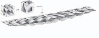
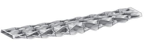
Diamanti182, 183, 184 represents a high-performance, resilient, and sustainable modular funicular structural spanning system developed through an integrated design approach combining 3D printing, concrete construction, and post-tensioning construction technologies (Figure 3.1.1). The structural form, determined by Polyhedral Graphic Statics (PGS), directly bears compression and tensile forces through its funicular geometry. Periodic anticlastic diamond surfaces are embedded within the thrust network to increase overall geometric stiffness and distribute shear loads. The porosity and increased surface area, derived from embedding diamond surfaces (Figure 3.1.2, p. 208), reduce the embodied carbon of the structure by limiting concrete consumption and enhancing carbonation potential. By taking construction and recyclability into account, the structure is designed as a modular system consisting of nine individual segments. Using a multi-component concrete mix, each segment was 3D-printed with a multi-axis industrial robot arm, ideal for fabricating the geometrically complex embedded anticlastic surfaces without formwork, further reducing the amount of construction materials required and waste produced (Figure 3.1.3,
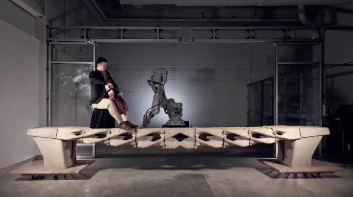
Fig. 3.1.1: Demonstration of structural elegance through a cellist’s performance on Diamanti. Enjoy DIAMANTI was an academia-industry collaborative project pushing the boundaries of architectural and engineering design. Photo credit: PSL.
To design Diamanti, a comprehensive computational methodology was developed that includes the use of advanced form finding, optimization, and volumetric modeling approaches, all of which address common fabrication and construction constraints. At the start of the design process, PGS,26, 185 a geometry-based structural design method, was used to determine a structure capable of dealing with both compression and tension forces (Figure 3.1.4). Hence, a compression-tension combined funicular geometric model was developed.183 Polyhedral cells, defined by the resulting geometric model, were used to contort and align periodic anticlastic surfaces along the identified principal stress directions. Specifically, the diamond Triply Periodic Minimal Surface (TPMS) was selected to address embedment and fabrication constraints (Figure 3.1.5) and served as inspiration for the name “Diamanti.” Signed distance function modeling186, 187, 188 was used as a final step in the design workflow to combine the funicular form and embedded anticlastic surfaces into a smooth, unified model for fabrication. The diamond TPMS unit geometry enhances the geometric stiffness of the structural form and inherently provides the internal conduits for the post-tensioned cables, resulting in a fully integrated material-structural system. Figure 3.1.6 illustrates the entire computational method as a workflow. The resulting final detailed design, including internal force and form diagrams, post-tensioning, and other construction details, is displayed in Figure 3.1.7.


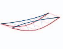


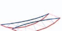


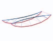


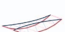

Fig. 3.1.4: form finding using PGS; (a) Minkowski Sum transformation in 3D is controlled by parameter ; (b)
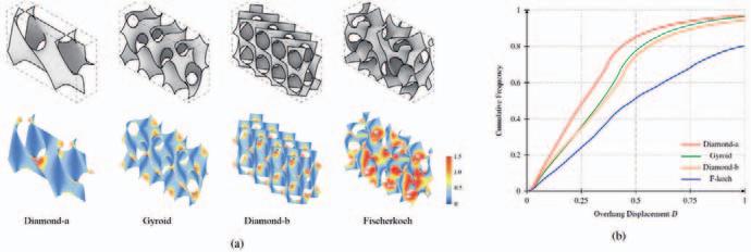
3.1.5: Selection of a periodic anticlastic surface based on an overhang study, considering fabrication constraints.
3.1.7: Final design with detailed section of the end module. Photo credit: PSL.
Fig.
Fig. 3.1.6: form finding and computational design workflow, adapted from Akbarzadeh et al.182 and Ororbia et al.184
Fig.
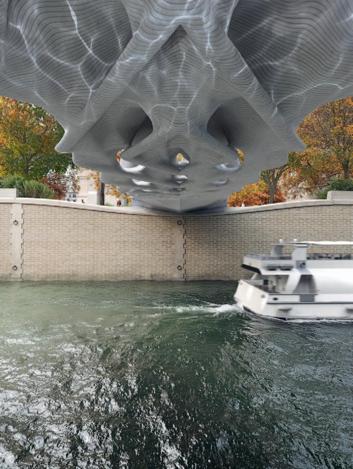
Fig. 3.1.19: (a) Underside view of the bridge from boat perspective. Courtesy of Massive Form.
Fig. 3.1.19: (b) Bridge deck with transparent glass panels exposing the underlying structure. Courtesy of Massive Form.
Masoud Akbarzadeh Author
4.2 MASS TIMBER STUDIO
Wood has served as an important building material for thousands of years due to its abundance, strength, and sustainable nature.214 Engineered mass timber, such as glue-laminated timber, cross-laminated timber, I-Joists, etc., includes products manufactured by binding or fixing the strands, fibers, veneers, or wood boards by applying adhesives to form composite materials. These products were developed to utilize material more efficiently due to the inherent variability (anisotropic properties) of wood-based systems.215 The main objective of these engineered products is to maximize durability, strength, and a high level of consistency as material properties.216
TYPE1TYPE2
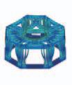
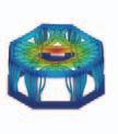
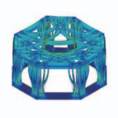
VonVonMiesDisplacement MiesDisplacement
TYPE3TYPE4
VonMiesDisplacementVonMiesDisplacement
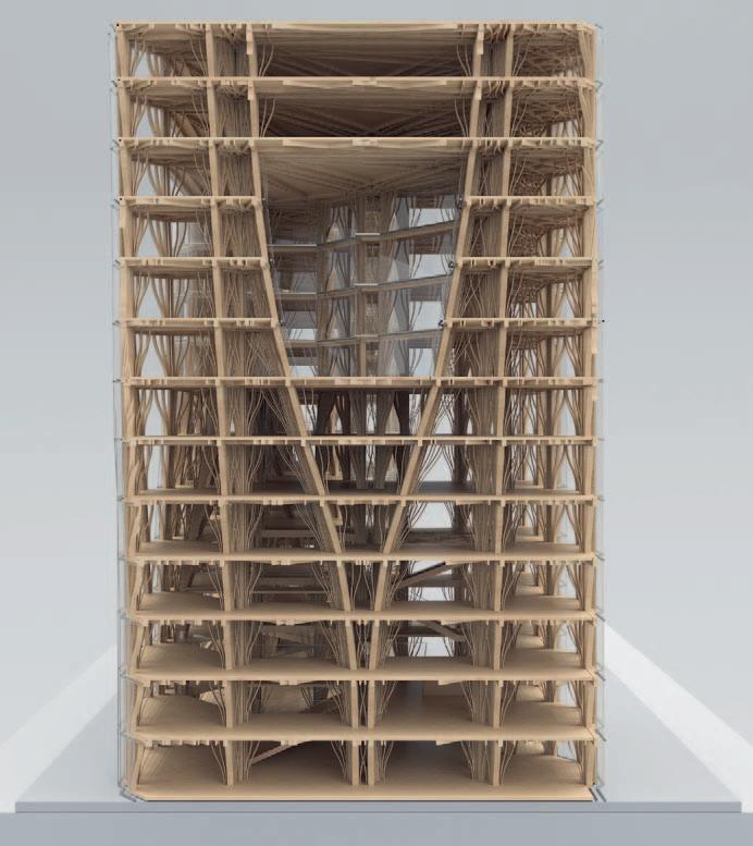
Fig. 4.2.46: Finite element analysis of the floor and column structure. Credits: Yujue Wang, Zechuan Yang.
Project Credits
The design content of this chapter was produced in a design research studio at the Weitzman School of Design taught by Dr. Masoud Akbarzadeh with the teaching assistance of Dr. Yao Lu.
Students: Sina Lee, Jingyi Chen, Yuze Deng, Jiaying Zhang, Yiliang Shao, Yuanben Gao, Zihao Jin, Wen Tian, Qiao Wang, Han Zhang, Yujue Wang, Zechuan Yang
Guest Critics: Martin Bechthold (Harvard GSD), Jeanette Kou (Karama + Kou, Harvard GSD), Nader Tehrani (NADAAA, Cooper Union), Marion Weiss (Weiss/Manfredi, UPenn), Tomás Méndez Echenagucia (Washington University), Homa Farjadi (UPenn), Richard Farley (UPenn), Dorit Aviv (TAL, UPenn), Laia Mogas-Soldevila (Dumo Lab, UPenn), Robert Stuart Smith (AML, UPenn), Florencia Pita (Sci-Arc)
Fig. 4.2.47: Section perspective of the building. Credits: Yujue Wang, Zechuan Yang.
Author
Masoud Akbarzadeh
Credits
All figures: Masoud Akbarzadeh
Except the following: Fig. 1.1.10, Fig. 1.3.18, 1.3.15: Damon (Mohammad) Bolhassani
Fig. 1.7.11, Fig. 1.7.12, Fig. 1.7.13: Jiyoon Bae, Thermal Architecture Lab
Fig. 1.7.15: Thermal Architecture Lab
Fig. 2.5.1, Fig. 2.5.5, Fig. 2.5.6, Fig. 2.6.3a-c: Dumo Lab
Fig. 2.1.1, Fig 2.1.26: Corning Museum of Glass
Drawings
Masoud Akbarzadeh
Editorial Team
Katja Pfeiffer, Anne Schäfer-Hörr (project management)
Cover design and layout
WVH Wiegand von Hartmann (Moritz Wiegand, Sophie von Hartmann, Maya Bendel)
Copyediting
Mark Kammerbauer, Munich (DE)
Proofreading
Alisa Kotmair, Berlin (DE)
Production and DTP
Roswitha Siegler
Reproduction
ludwig:media, Zell am See (AT)
Printing and binding
Gutenberg Beuys Feindruckerei
Paper
Artogloss (cover), Magno Volume (content)
Publisher
DETAIL Architecture GmbH
Messerschmittstr. 4, 80992 Munich (DE) detail.de books@detail.de © 2025, first edition
ISBN 978-3-95553-650-3 (Print) ISBN 978-3-95553-651-0 (E-Book)
Bibliographic information published by the German National Library. The German National Library lists this publication in the German National Bibliography (Deutsche Nationalbibliographie); detailed bibliographic data is available online at http://dnb.d-nb.de.
This work is subject to copyright. All rights reserved. These rights specifically include the rights of translation, reprinting, and presentation the reuse of illustrations and tables, broadcasting, reproduction on microfilm or any other media; and storage in data processing systems. Furthermore, these rights pertain to any and all parts of the material. Any reproduction of this work, whether in whole or in part, even in individual cases, is only permitted within the scope specified by the applicable copyright law. Any reproduction is subject to charges. Any infringement will be subject to the penalty clauses of copyright law. This textbook uses terms applicable at the time of writing and is based on the current state of the art, to the best of the authors’ and editors’ knowledge and belief. No legal claims can be derived from the contents of this book.
Cover drawing
Masoud Akbarzadeh