Rail Engineer - Issue 216 | September - October 2025
Derby’s GREATEST
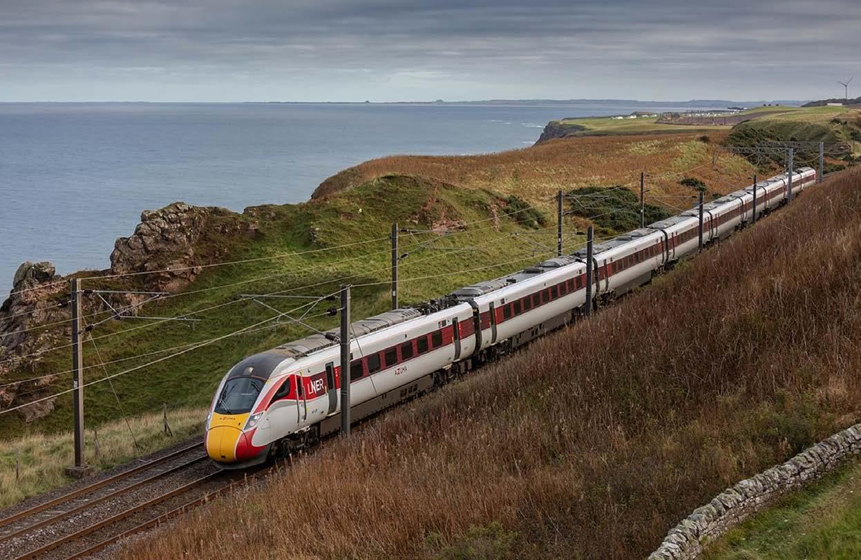
ECML investment bears fruit
£4 billion worth of upgrades will deliver major capacity gains as a new December timetable boosts services, speeds, and revenue.
Derby’s greatest gathering
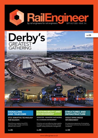
Alstom’s Derby works hosted Britain’s biggest ever rail showcase, uniting 140 historic and modern vehicles for Railway 200.
MyPeople Group: transforming safety cultures
Behavioural intelligence specialist MyPeople is helping rail companies like Network Rail build safer, higherperforming teams through data-driven insights. 22|
Gripple SwiftLine: a one-stop shop for OLE Installation
Gripple offers a complete OLE installation system which is faster, safer, and simpler.
ETCS Implementation issues
Malcolm Dobell examines the technical and operational challenges of ETCS implementation and how unresolved issues could impact UK rail capacity.
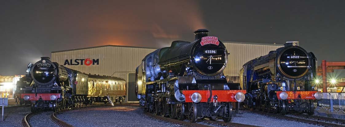
ETCS: Disruptive technology for railways
David Fenner discusses how this disruptive technology, can deliver safer, simpler, and more efficient train control.
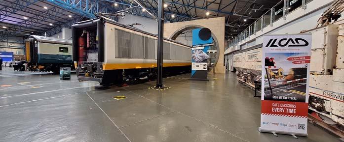
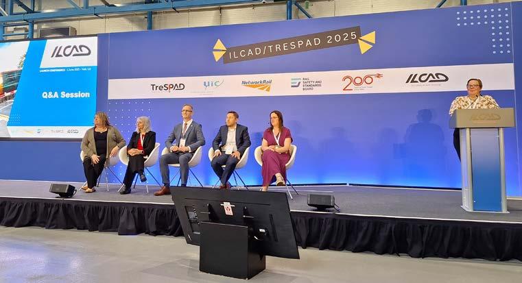
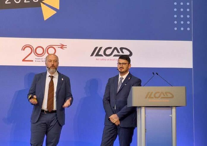
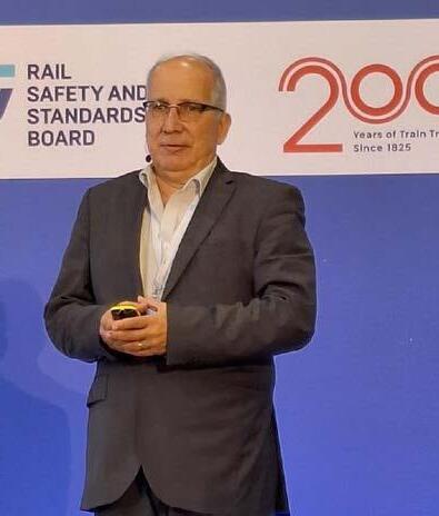
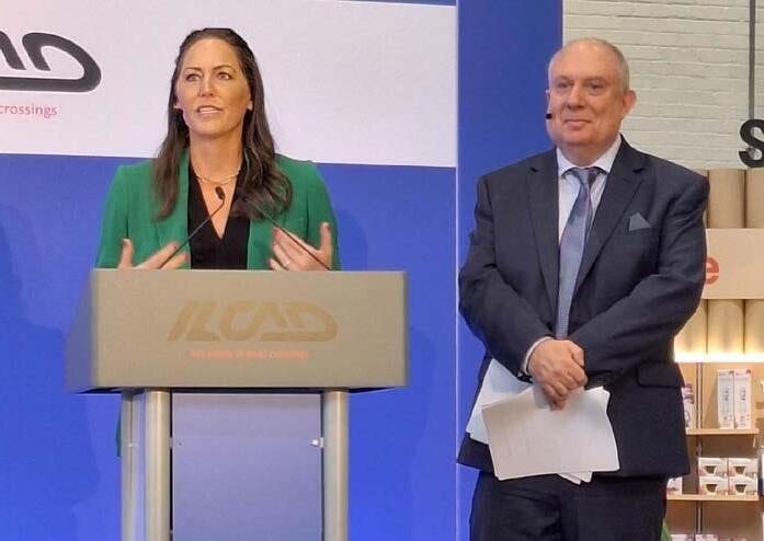
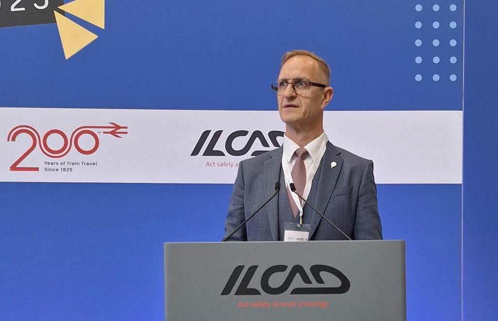
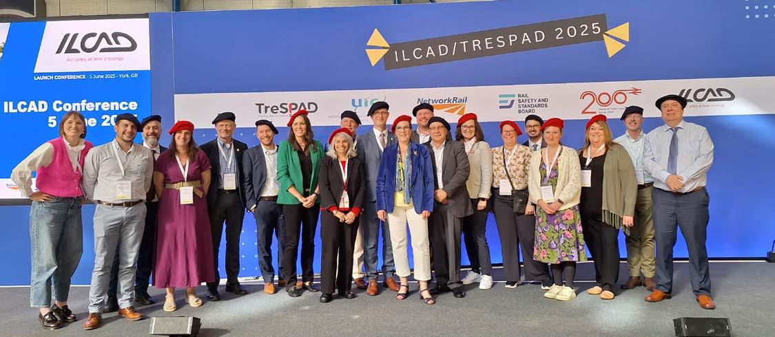
International Level Crossing Awareness Day
Global rail and road safety experts united in York for ILCAD 2025, sharing their ideas to reduce level crossing incidents.
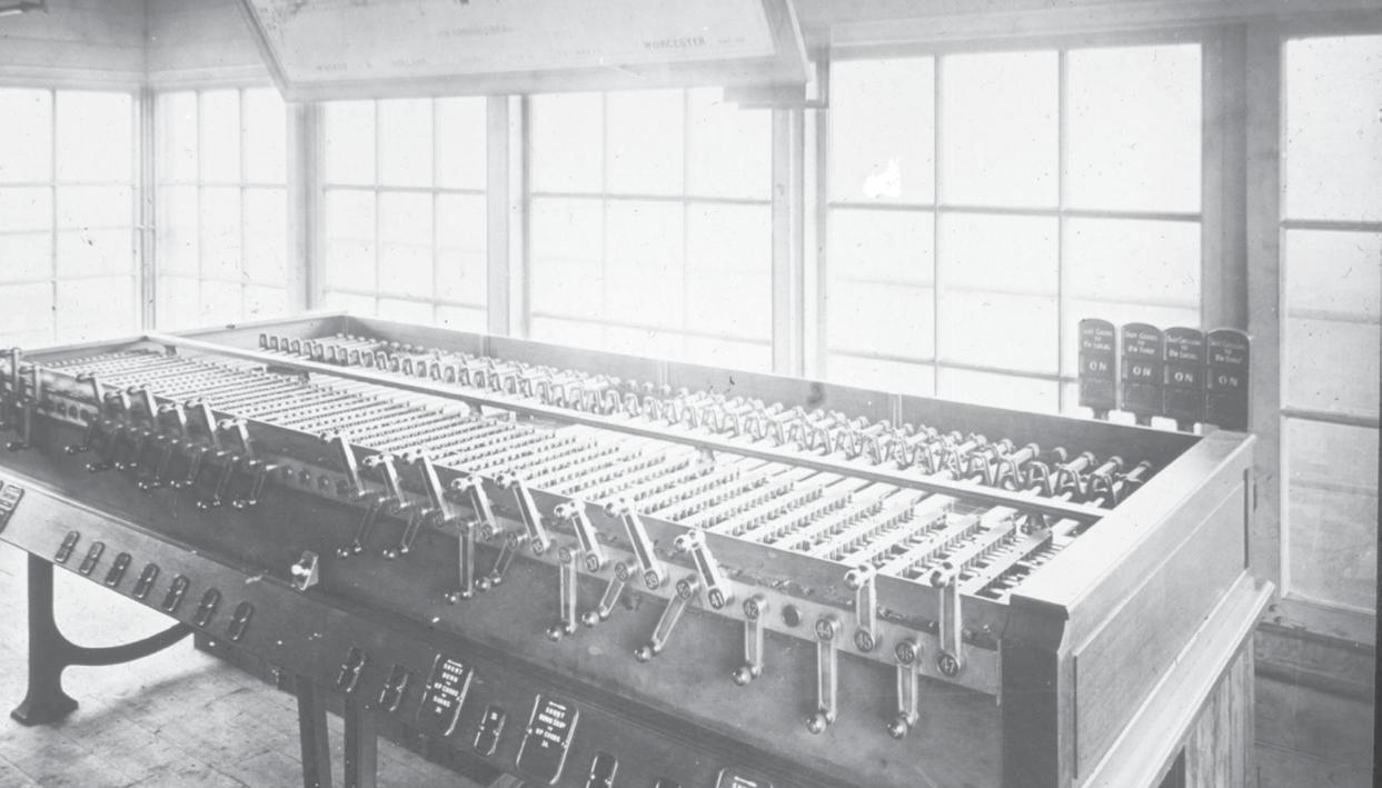
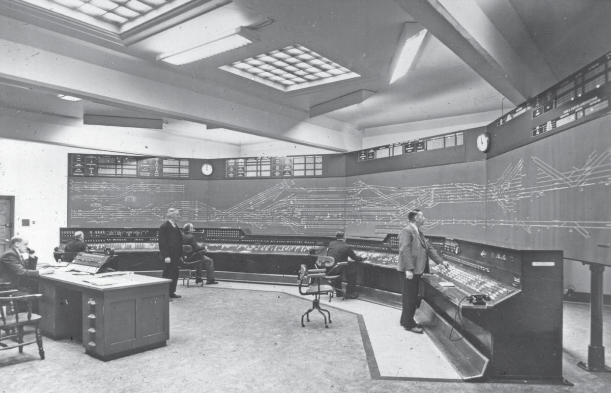
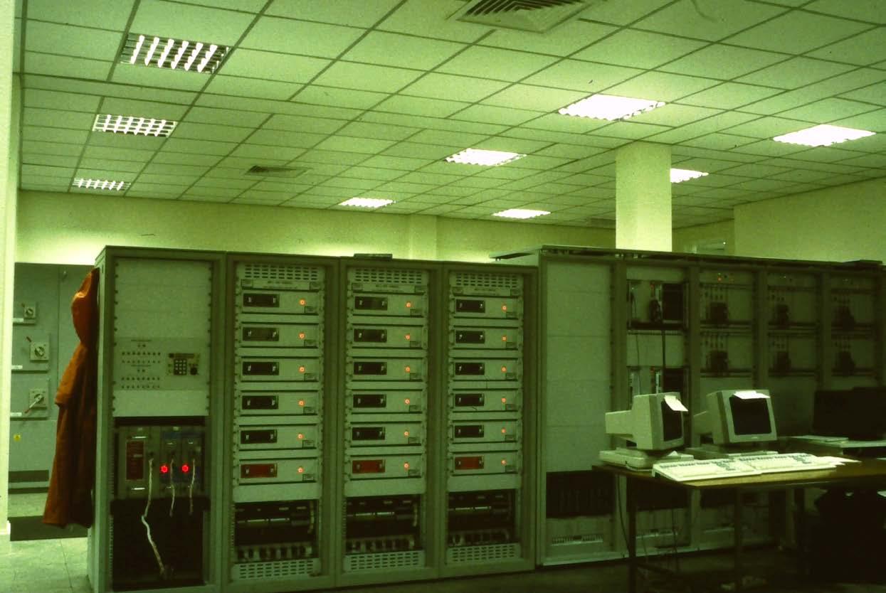
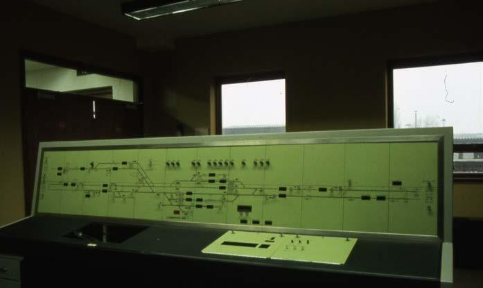
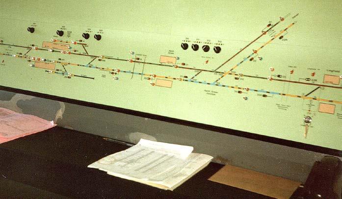
Railway 200: signalling post-1900
Paul Darlington charts the evolution of railway signalling from 1900 to the present, exploring key technologies shaping modern train control.
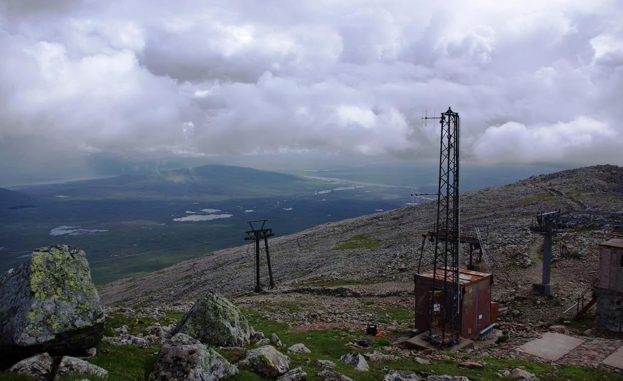
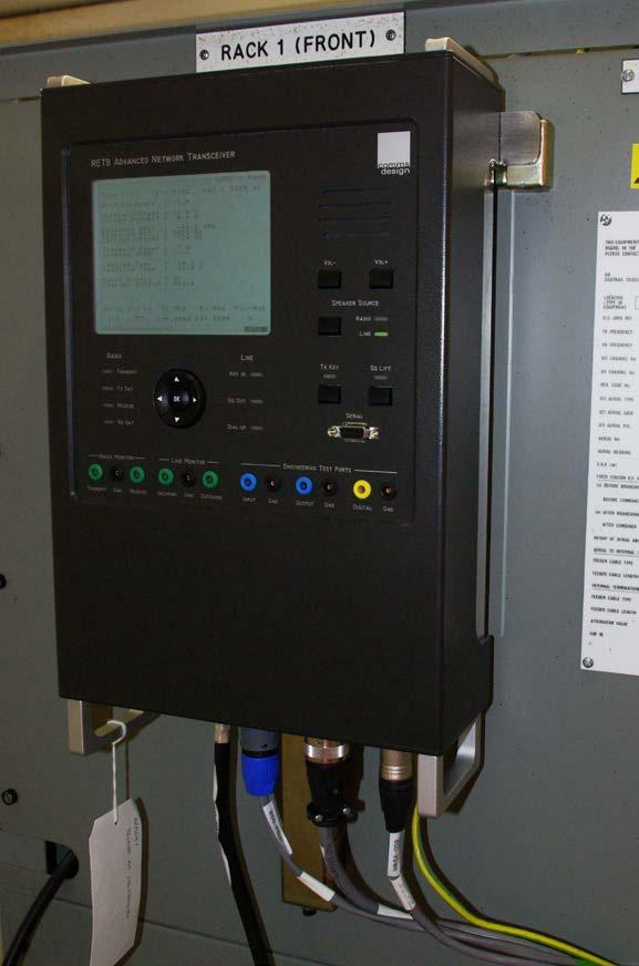
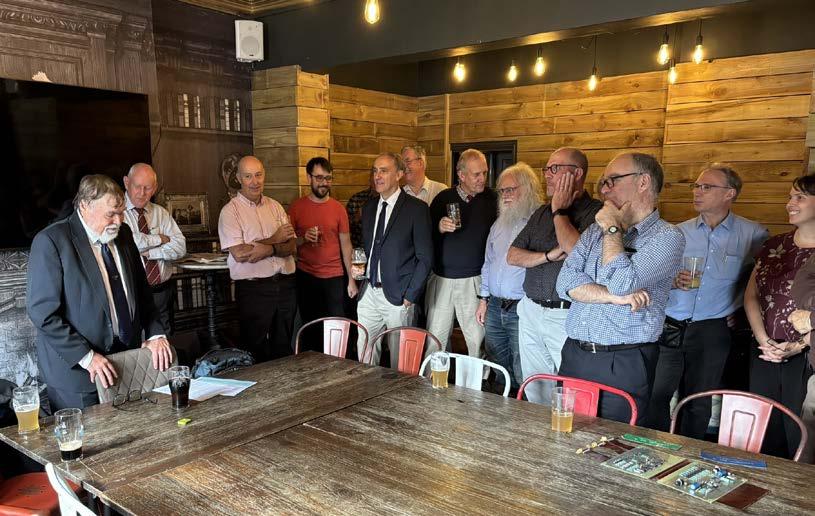
RETB 40 years on
Marking 40 years of Radio Electronic Token Block, Clive Kessell traces its origins, evolution, and enduring role on remote lines.
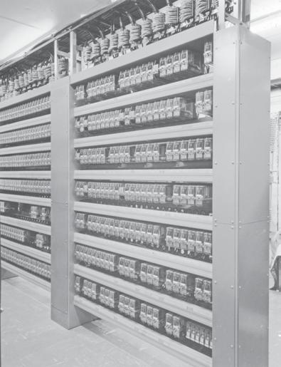
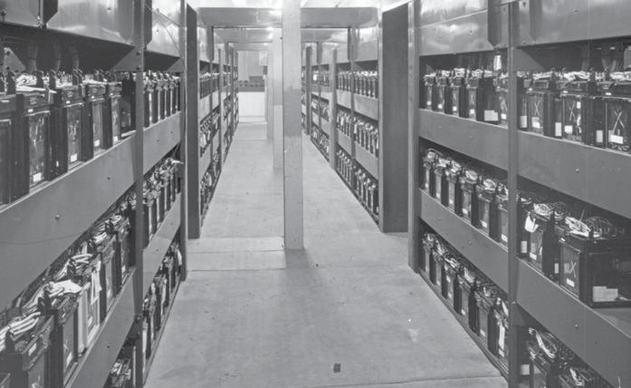
Forty years of Solid State Interlocking
Drainage monitoring in a changing climate
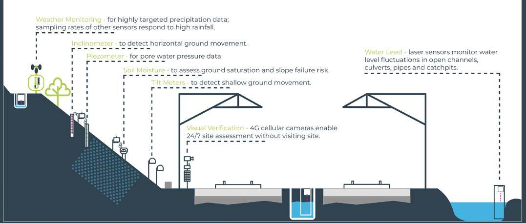
Senceive’s wireless monitoring technology provides realtime drainage data for safer, more resilient infrastructure.
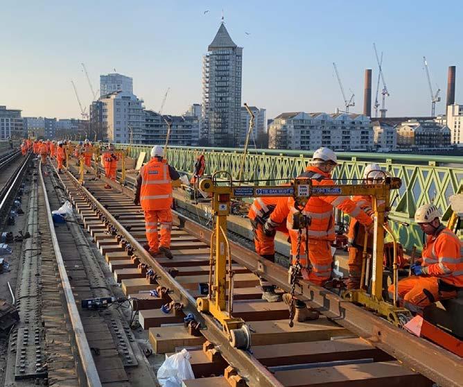
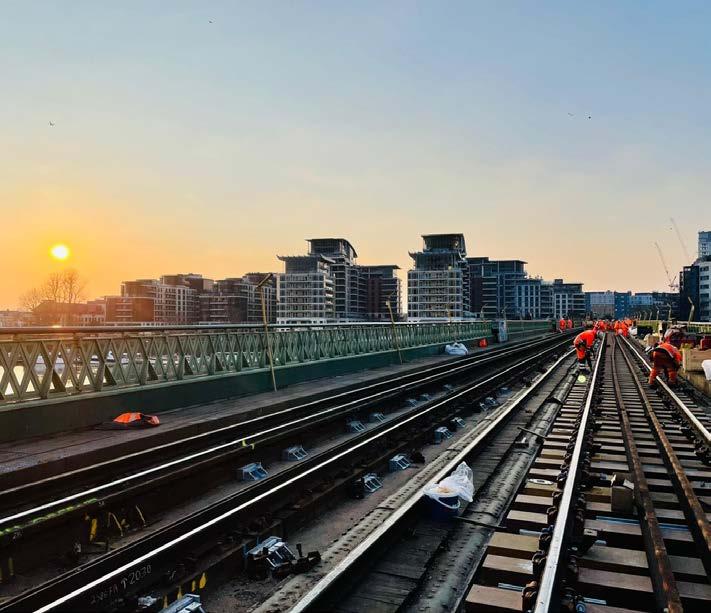
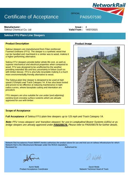
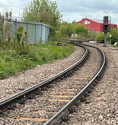
FFU Plain Line Sleepers get greenlight in UK and Ireland
Sekisui’s FFU sleepers offer durability, sustainability, and proven global performance.
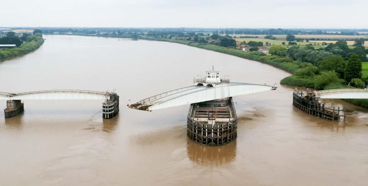
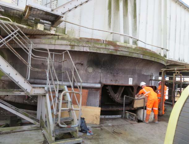
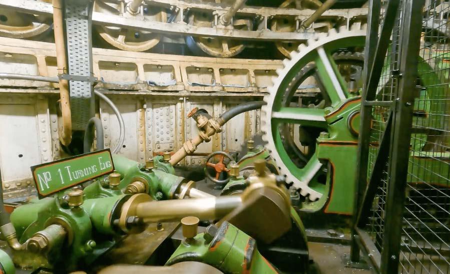
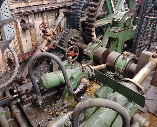
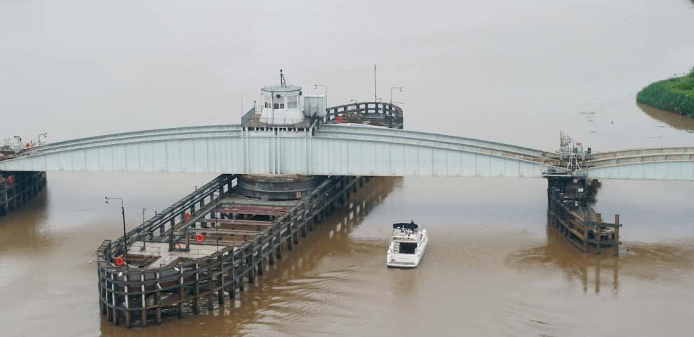
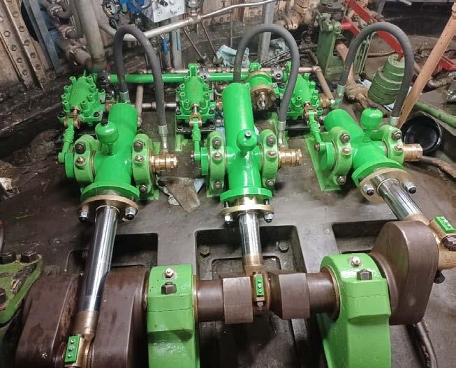
Goole Swing Bridge mechanical refurbishment
A programme of refurbishment has preserved Goole Swing Bridge’s Victorian hydraulic systems, enhancing reliability, control, and longevity for future operations.
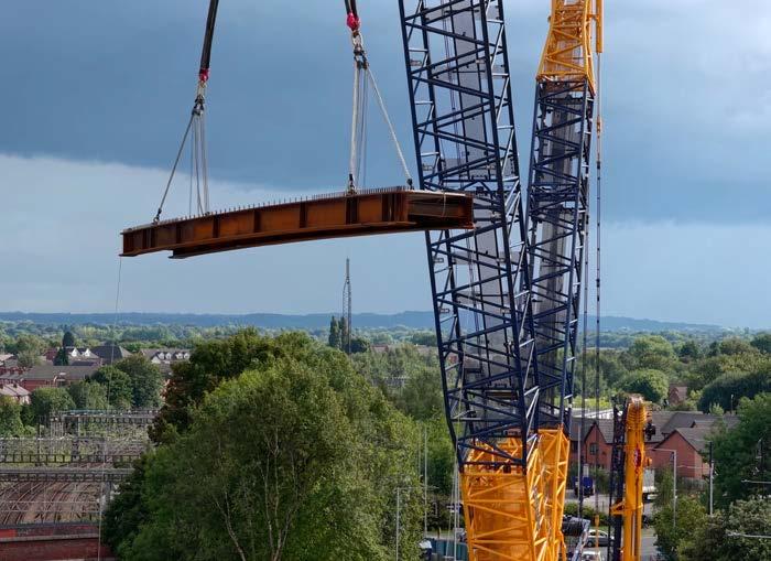
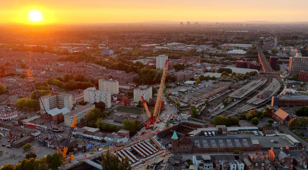
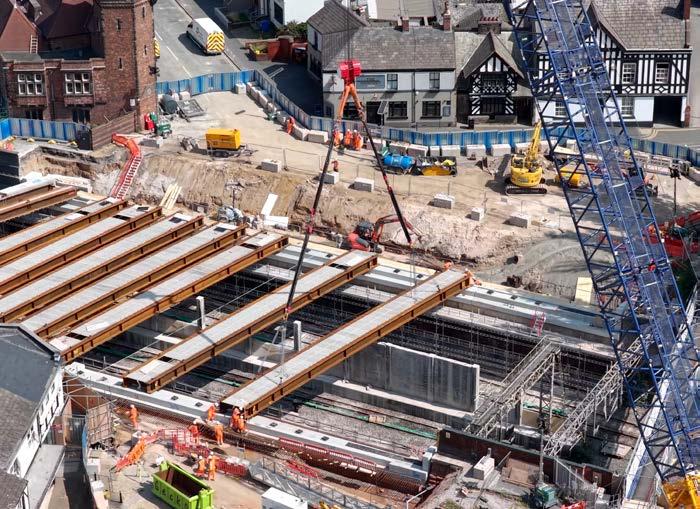
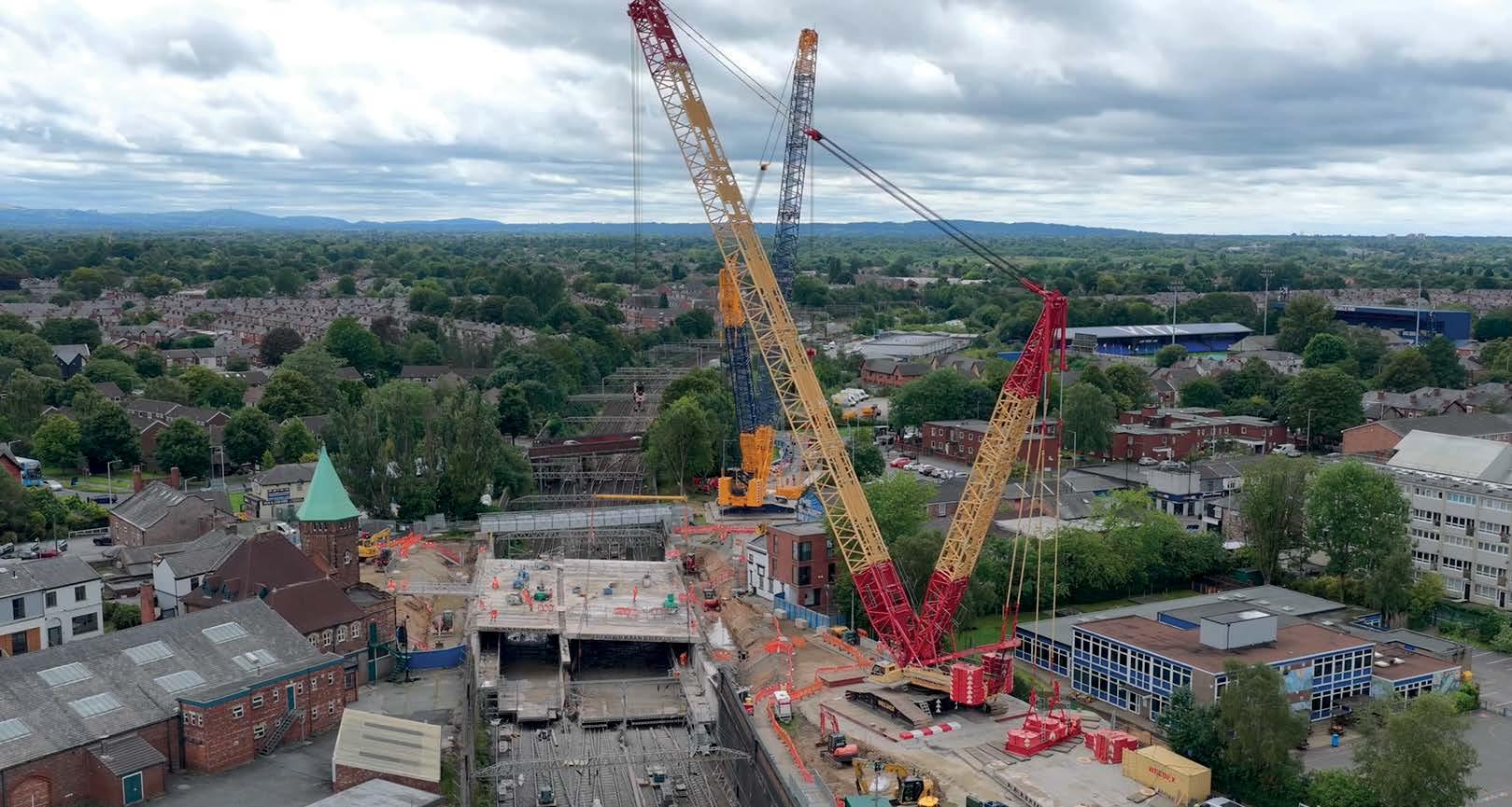
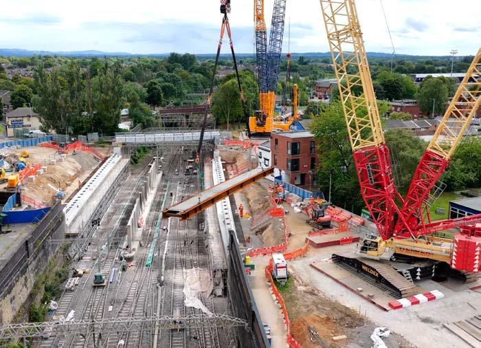
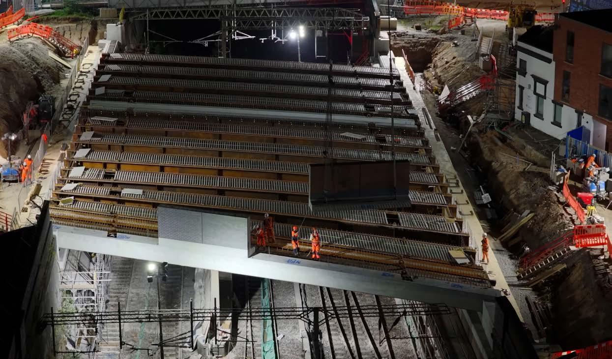
Greek Street railway bridge rebuild Greek Street bridge in Stockport was rebuilt over 21 days to enhance safety and capacity for the next 120 years.
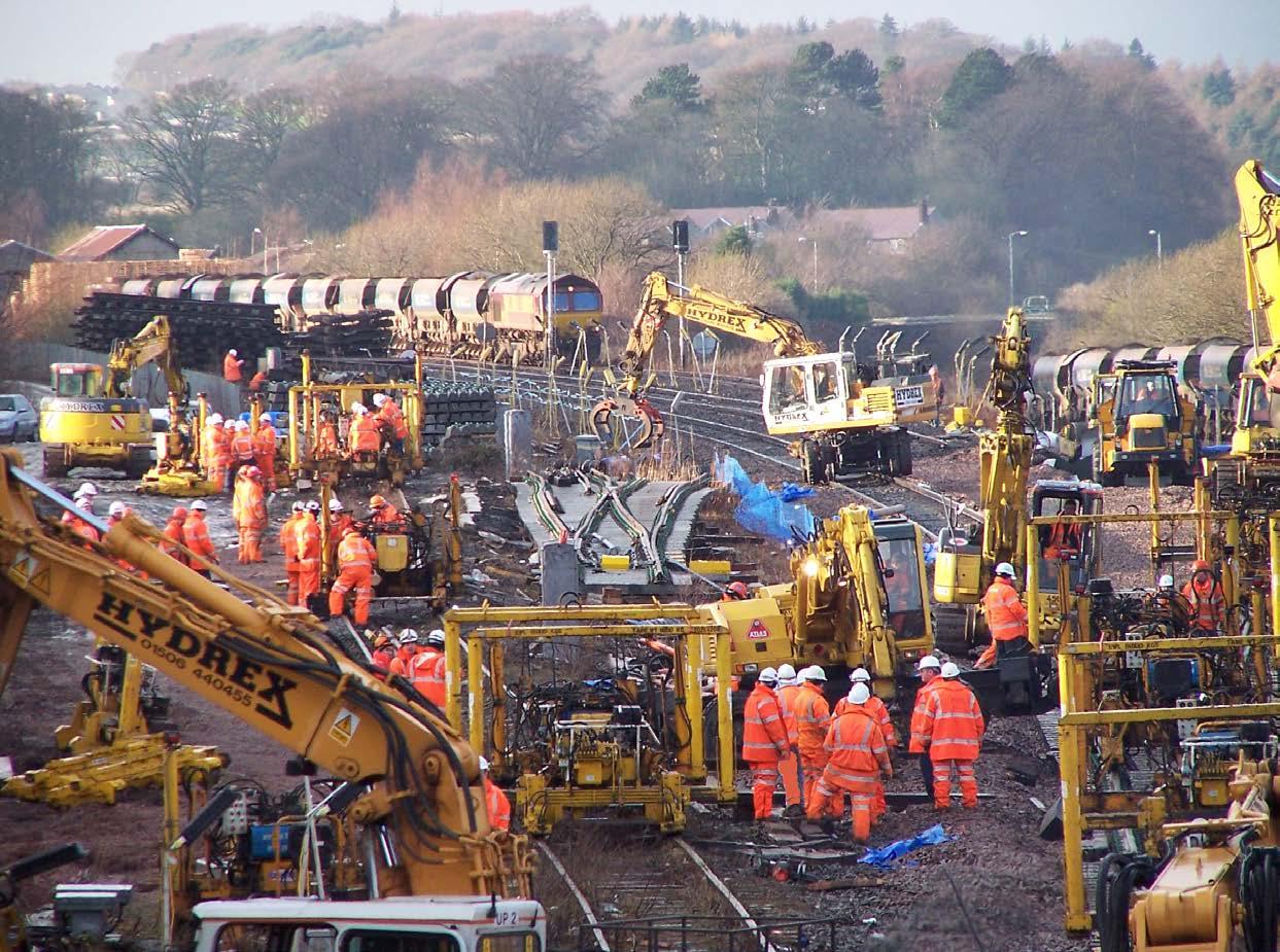
Improving track worker safety
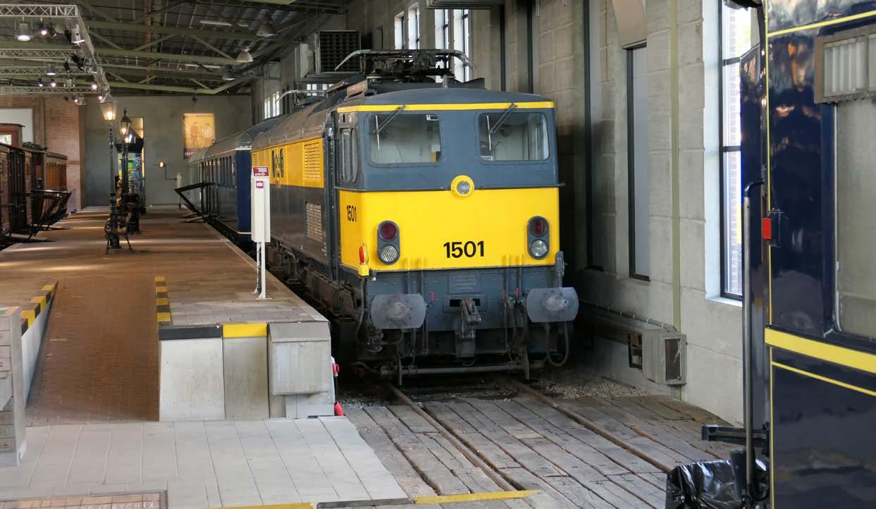
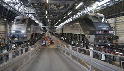
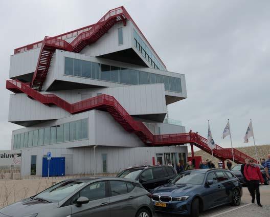
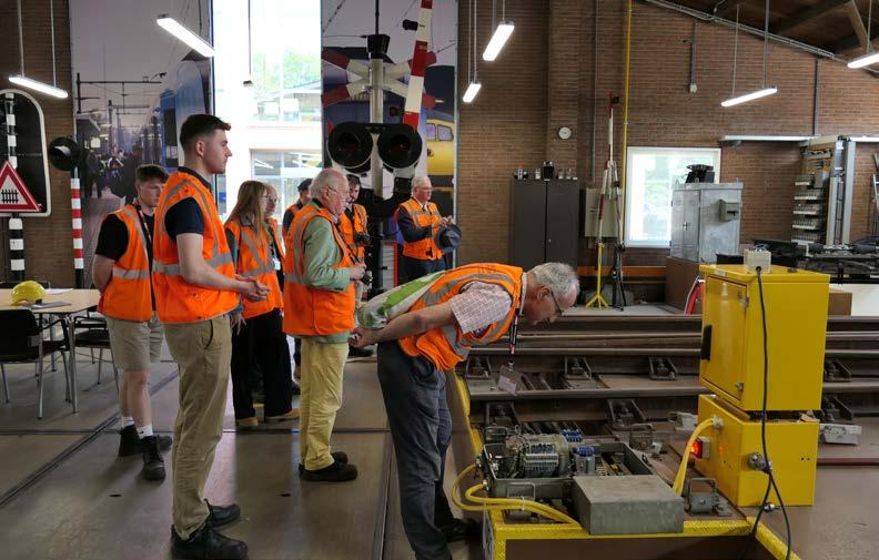
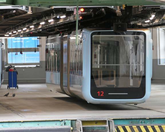
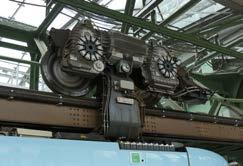
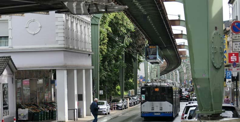
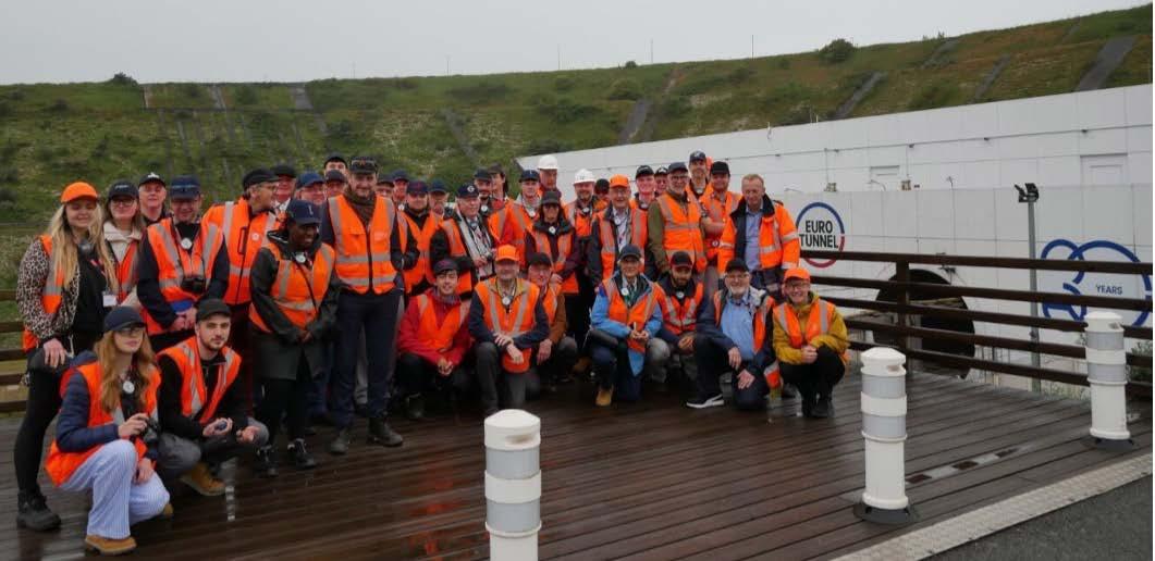
An eight-day European tour offered engineers first-hand exposure to bogie plants, stations, monorails, and more. 40|
We also celebrate 40 years of Solid State Interlocking, the groundbreaking British Rail innovation that revolutionised global signalling technology.
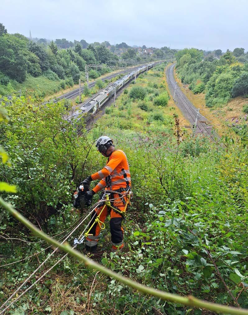
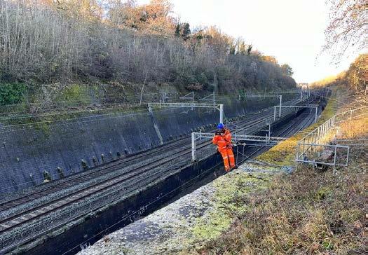
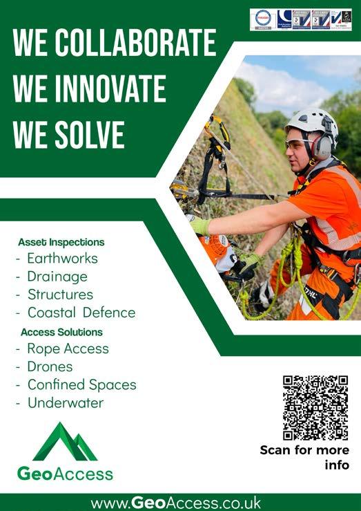
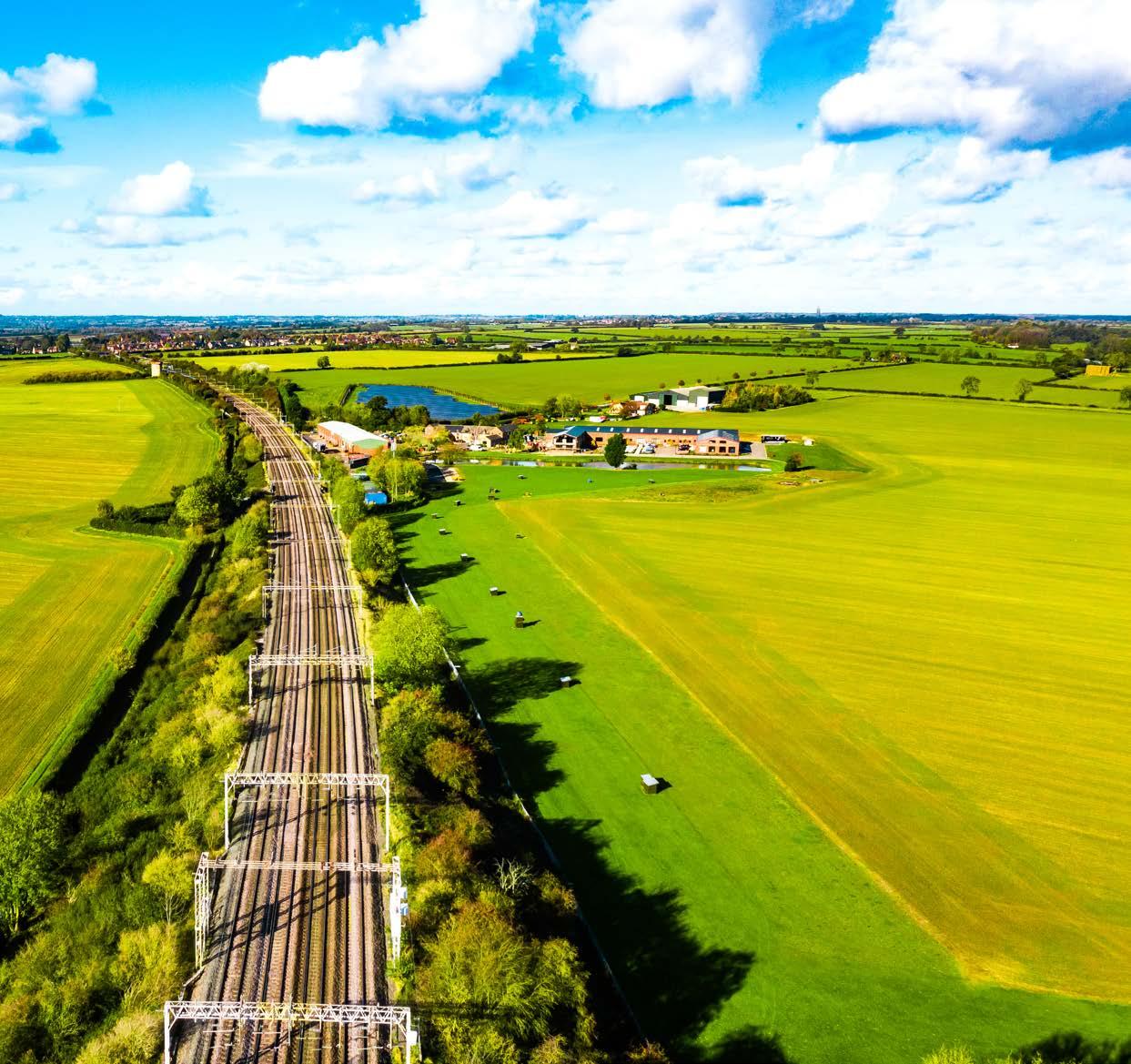
GeoAccess - managing earthworks in a changing environment
David Howard discusses railway earthworks management in a changing climate with wetter winters.
Key takeaways from RIA’s Environment and Sustainability Group
The event explored procurement reform, decarbonisation, and supply chain innovation for a more resilient railway.
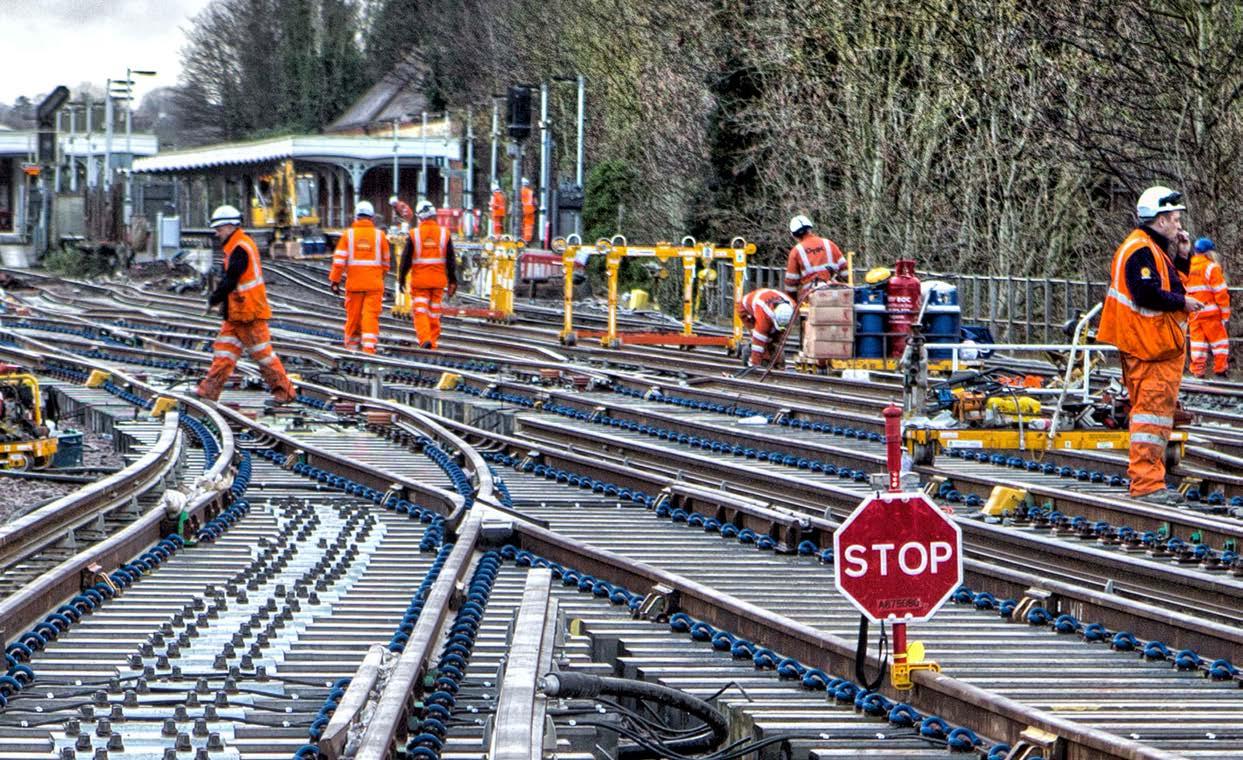
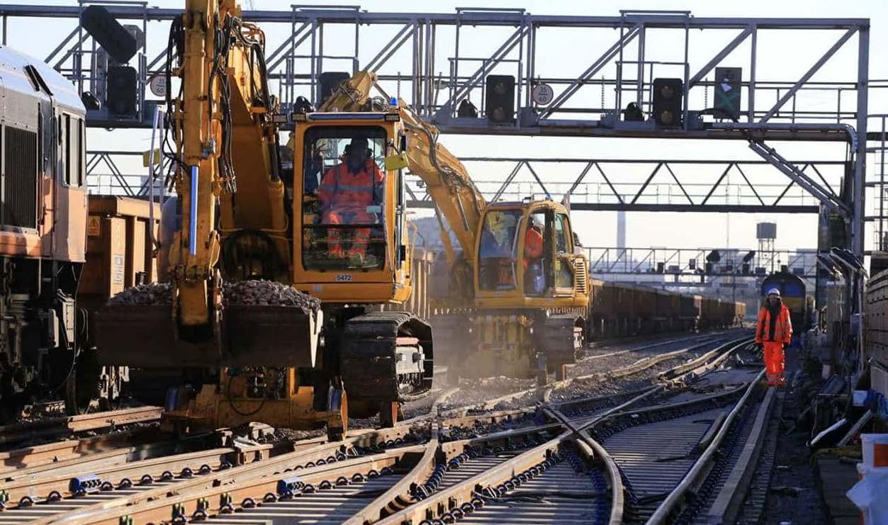
Advanced technologies, geolocation, and remote protection are transforming trackside work, reducing risk and improving safety for workers.
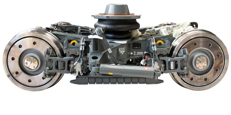
Magnetic track brakes to Monorails: the IMechE Railway Division Technical Tour
Engineering good connections: IMechE Railway Division Chair’s Address
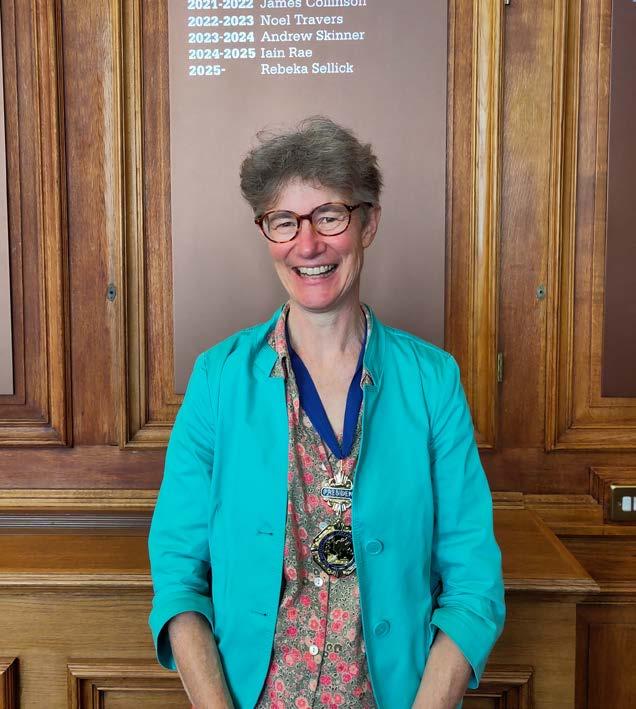
Rebeka Sellick encouraged engineers to connect people, technology, and policy.
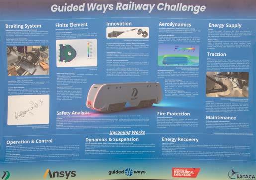
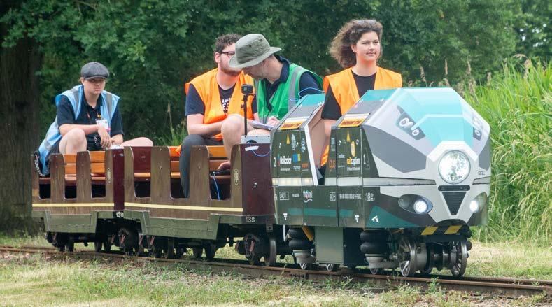
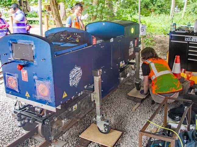
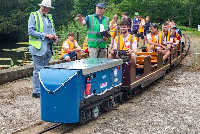
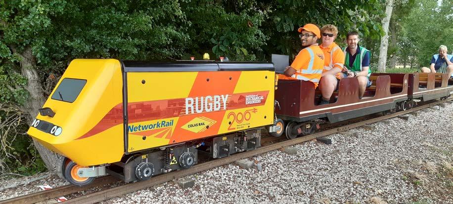
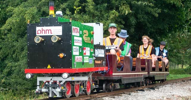
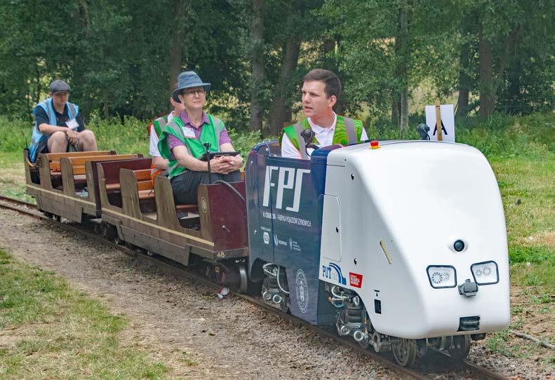
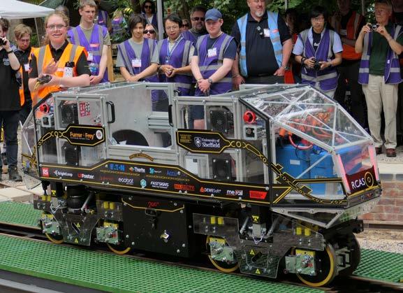
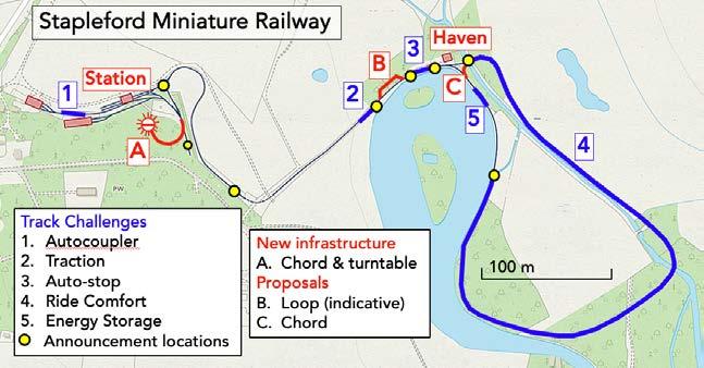
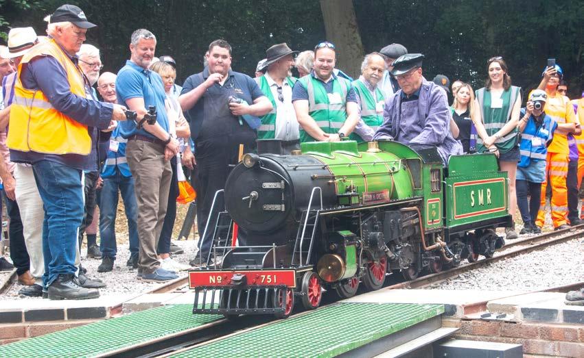
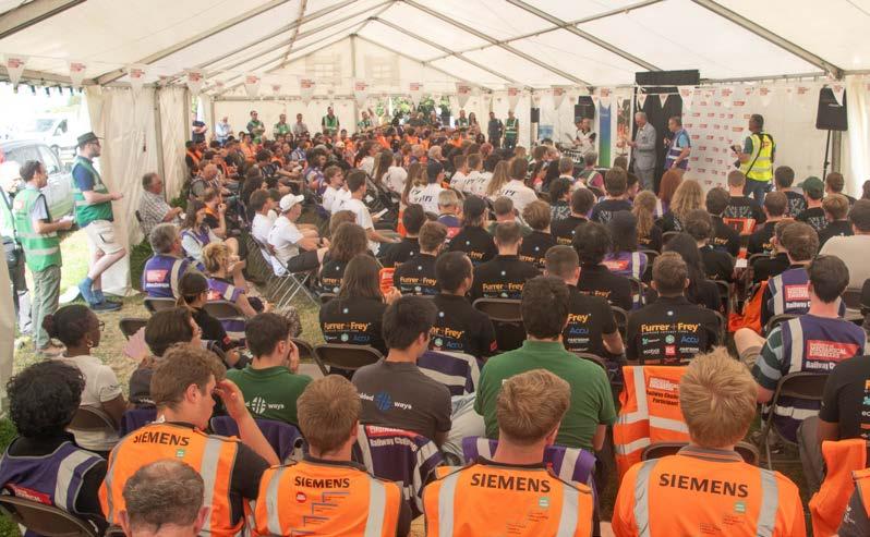
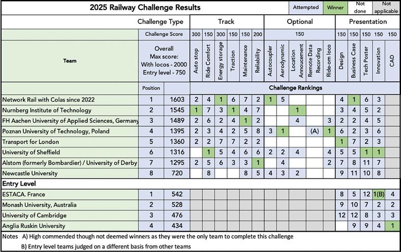
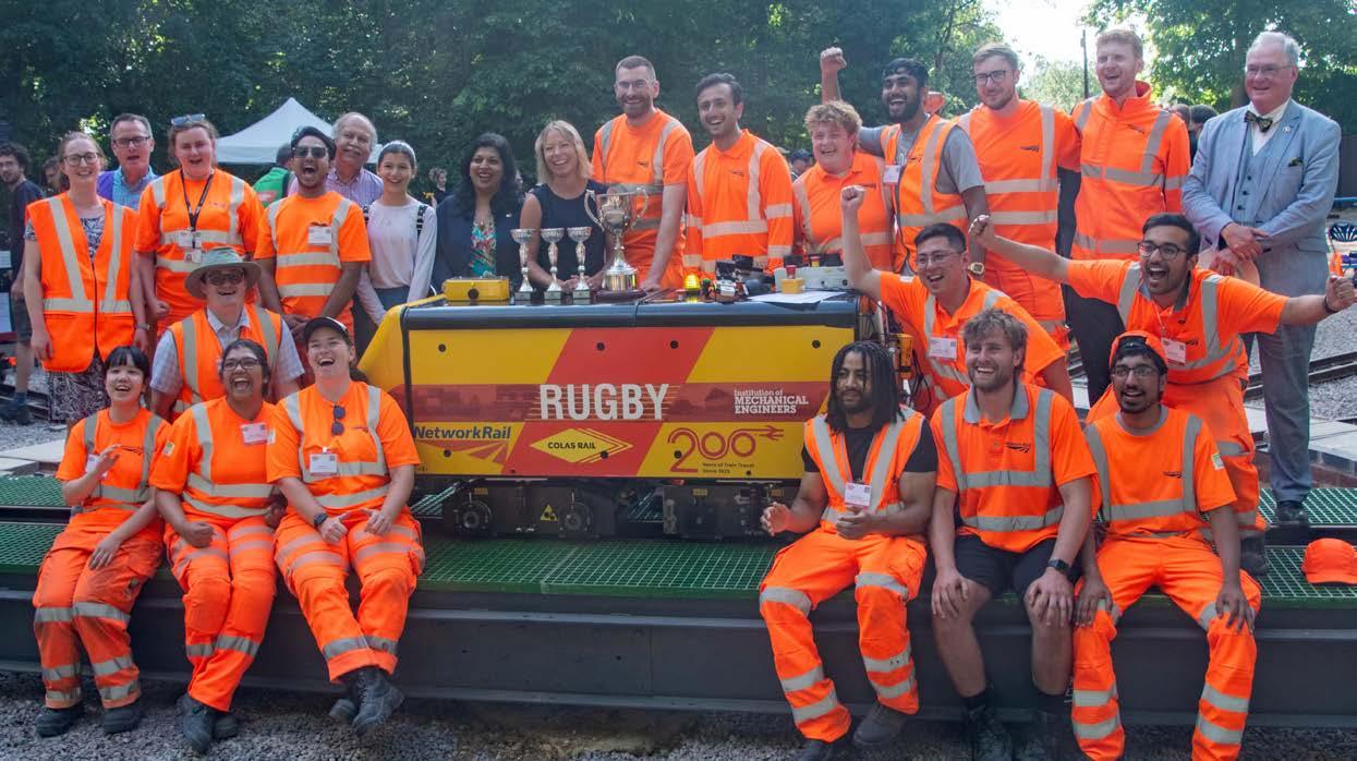
The 2025 Railway Challenge Network Rail and Colas triumphed at the IMechE Railway Challenge, as international teams showcased innovative locomotives and their engineering skills.
Two alternative futures
As we celebrate Railway 200, we consider what the future holds for Britain’s railways. In doing so we imagine two quite different possibilities.
One possible future envisages intolerable road congestion and increasingly common extreme climate events, that will make it politically acceptable to tax HGVs, motorists, and flights to encourage model shift to rail. With a strong cross-party consensus that rail investment generates significant economic returns, a huge programme of railway investment drives a significant economic upturn.
As a result, by 2125 the original HS2 ‘Y’ network, Northern Powerhouse Rail, and other new lines will have been built. In addition, all main lines and key freight lines have been electrified and signalled by ETCS. Investment in light rail and local bus networks, together with seamless through ticketing, will offer easy door-to-door journeys. As a result, passenger and freight rail traffic volumes are three times those of 2025 and rail accounts for 25% of all passenger and freight traffic. This modal shift to net-zero electric trains will also significantly reduce UK transport carbon emissions.
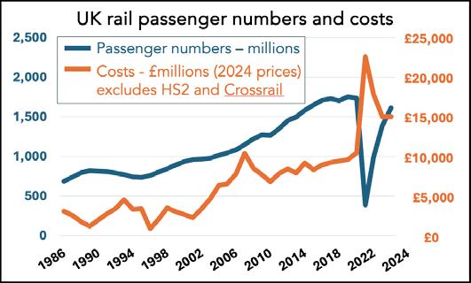
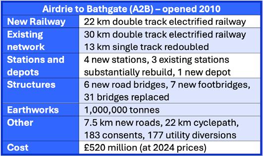
A quite different future is envisaged by a respected engineer who told me that in 100 years’ time railways will be footpaths as rising costs will have driven them out of business. Though it is difficult to accept this extreme scenario, the railway’s cost to the taxpayer is currently over four times more than at privatisation in 1994 and rising project costs have curtailed HS2 and railway electrification. As an example, readers are invited to estimate the cost of the deliverables of the 2010 A2B project and compare this with its £520 million cost at today’s prices.
In this future, high costs reduce the Government’s appetite for rail investment. Hence, by 2125, there will have been few, if any, significant new enhancement projects, very little new electrification, and the digital signalling programme will have stalled. The rise in rail
passenger and freight traffic peaked around 2050 as no more trains could be accommodated on the network. Hence by 2125, rail traffic will then have fallen to 5% of all passenger and freight traffic.
Though these alternative futures are two extremes, they illustrate the point that railways have the potential to transform the UK economy, just as they did in the past. Yet the extent to which they can do so depends on government investment which, in turn, depends on whether the industry can deliver affordable projects.
These visions of the future do not mention innovations. Modern technologies such as AI and improved data management will no doubt improve efficiency and customer experience. However, for the past 200 years the railways have been engineered to be the most efficient form of transport for large volumes of traffic in respect of energy use, capacity, and land take. This will always be the case as these inherent benefits derive from the laws of physics which will not change in the future.
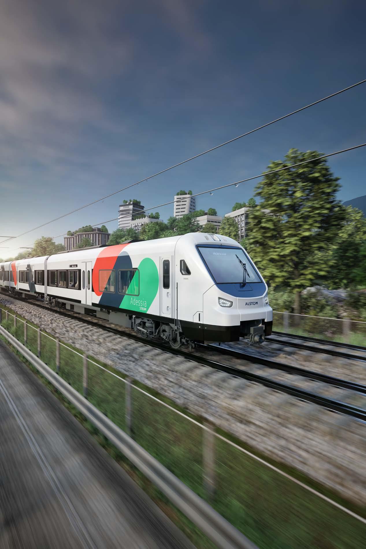
For this reason, these benefits should be better promoted. It was, for example, disappointing that there was no explanation of why railways are so efficient in the otherwise excellent Railway 200 inspiration train. Alstom’s greatest gathering was literally a huge celebration of the railways’ 200th year. As we report, its many rail vehicles showed how rolling stock had developed over the years as well as showcasing modern railway technology.
As part of our signalling focus in this issue, we have a Railway 200 feature in which Paul Darlington considers developments in signalling since 1900. We report on the groundbreaking introduction of Signalling Solid State Interlocking (SSI) 40 years ago, while Clive Kessell describes the first use of Radio Electronic Token Block (RETB), also introduced 40 years ago.
Level crossings are a challenge for signalling engineers as shown our report on the 17th International Level Crossing Awareness
Day. A common theme of the need to take account of human behaviour was shared by representatives from Japan, Argentina, Canada, USA, and many European countries.
The signalling system is now being used to eliminate the historic (and risky) practice of using detonators to protect possessions. Our feature describes this and other current track safety improvements such as geolocation that will both improve track safety and deliver productivity benefits.
ETCS cab signalling also brings safety and productivity benefits. In a comprehensive feature, David Fenner describes why it is such a disruptive technology with initial high costs. He explains why, though its capacity benefits are small, ETCS will eventually offer significant benefits. In another feature, Malcom Dobell explains how ETCS does not yet take account of differential speed limits, axle-loadrelated speed restrictions, and the braking characteristics of different locomotive-hauled train formations.
Although the railways’ civil engineering dates back to its origins, very few operational assets are that old. One is described by Bob Wright in his feature about the recently completed renovations of the railway swing bridge over the River Ouse at Goole which is powered by 157-year old hydraulic machinery. This required reverse engineering and Historic England’s agreement for changes to the original machinery. We also report on the major work to replace the 67-year-old bridge over the railway at Greek Street in Stockport. We have three reports on the activities of the IMechE’s Railway Division which does much to support young engineers. To date, over 1,200 young engineers have benefited from the experience they gain from competing in the Railway Challenge. Our
report on the 13th challenge shows it always offers something new. We also report on the Division’s action-packed technical tour to Netherlands, Germany, and France on which around 20 young engineers learnt much about railway engineering in Europe.
Engineering good connections is the title of the Railway Division’s Chair’s address. This year’s chair, Rebeka Sellick, used the word ‘connections’ in various different contexts: the need to link different parts of the railway system; better communications between different parts of the railway; and providing passengers with connected journeys. She also urged engineers to connect with decision makers to convince them of what the railway offers.
As part of our Sustainability and Environment focus we report on the Railway Industry Association (RIA) Environment and Sustainability Group as well as managing earthworks and drainage monitoring. The common theme of these articles is taking effective action to address climate change which is now a reality.
Finally, as Andrew Haines retires from his post of Network Rail’s CEO after seven years, Rail Engineer would like acknowledge his contribution to the industry. Among many other things he has made Network Rail a more customer-facing organisation and paved the way for rail reform. I remember Andrew for his honest, off-the-record press briefings which provided invaluable background information. We wish him well in his retirement.
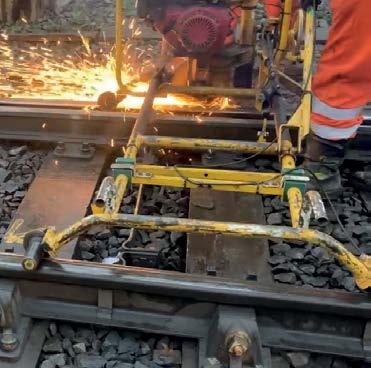
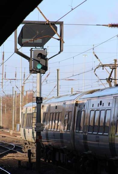
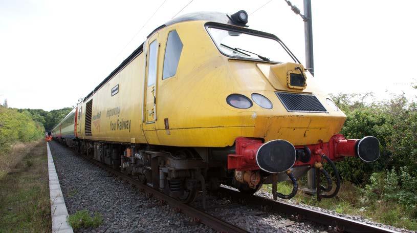
(Below) Signal being removed from ETCS signalling Northern City Line.
Editor David Shirres editor@railengineer.co.uk
Production Editor Matt Atkins matt@rail-media.com
Production and design Adam O’Connor adam@rail-media.com
In recent times £4 billion has been invested in rolling stock and infrastructure on the East Coast Main Line (ECML). Infrastructure works have included power supply upgrades, the remodelling of Kings Cross station, and the dive-under at Werrington. Though these are impressive infrastructure projects, their benefits cannot be fully realised until the ECML has a timetable that makes best use of the capacity created by these projects.
Production of the new ECML timetable that is to be implemented in December was a complex task not least because there are not enough train paths to satisfy the demand of passenger and freight operators. Furthermore, the impact on train performance has to be considered. If all available train paths are used, minor delays will result in widespread disproportionate knock-on effects.
It has taken five years to develop this timetable which required the reconciliation of stakeholder aspirations and extensive modelling. Network Rail advised the largest ever form simulation model ever done in industry, as well as the use of signalling system simulators. This modelling predicts a 1.9% reduction in train performance which is considered acceptable given the extra capacity created. Lessons from the disastrous 2018 timetable introduction have also been addressed including a phased introduction, contingency plans, and detailed resource planning (driver diagrams, rolling stock allocation).
The new timetable will offer an extra 16,000 seats per week to generate extra revenue of £60 million per annum. It offers a 33% increase in train paths for long-distance high-speed services between London and Doncaster with a 20% increase between Doncaster and Newcastle. There will also be faster journey times between London and Edinburgh. The number of LNER trains from Kings Cross increases from five to six per hour.
As well as improved ECML fast services, there is to be a new Northern Train fast service between Leeds and Sheffield, extra Govia Thameslink suburban services, and an hourly East Midland Trains Lincoln to Nottingham service. There is to be a phased introduction of some of the new service. This makes the timetable introduction more manageable and also defers some new CrossCountry services until after a TransPennine Route Upgrade blockade.
One way of ensuring capacity is the shortening of the Leeds locomotive-hauled services from nine to seven coaches to give them the same performance characteristic of the Azuma trains. The resultant loss of seats on this service is addressed by other trains providing an improve service between London and stations south of Doncaster served by the Leeds trains.
Although the timetable offers significant improvements, some stakeholder aspirations have not been met. In particular there has been no increase in freight paths. At the press briefing for the new timetable, it was stated that “we will struggle for additional capacity between 06:00 and 22:00” and that “additional access rights will be considered carefully due to performance constraints.” It would seem, then, that the new ECML timetable offers little, if any, scope for additional train paths and is, in effect, full up.
Thus, a further significant timetable enhancement will require infrastructure work to improve capacity particularly on the two-track ECML sections. While Network Rail is undertaking capacity studies to determine the infrastructure enhancements required to release extra capacity, there is currently no funding for any such work.
At the press briefing it was clear that Network Rail’s view is that the first step for us is to make this timetable a success, to prove to the government that its previous ECML investments are now generating revenue. Hence the success of this timetable is key to making the case for future investment.
DAVID SHIRRES
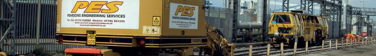
Pearsons Engineering Services is a well established railway maintenance company specialising in the inspection, repair and maintenance of railway infrastructure and the installation of new railway facilities.
• Railway track inspection and examination
• Railway track maintenance
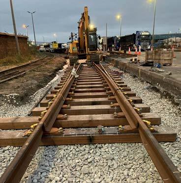
• Railway track repairs and renewals
• S&T inspection, repairs and maintenance
• Drainage solutions
• Vegetation control (Herbicide application)
• Site surveys
• Minor civil engineering works
• Crane rail inspections and repairs
• 24-hour callout facility
• Consultancy services available for any of the above Services offered
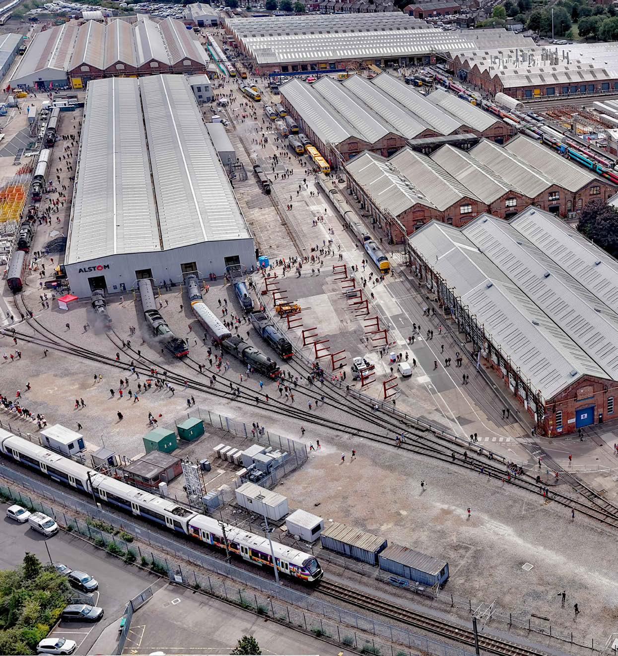
Derby’s
GREATEST GATHERING
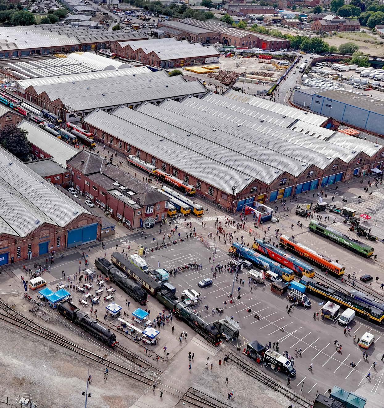
In its 150-year history, it is unlikely that the 90-acre railway workshops at Derby Litchurch Lane have ever welcomed 40,000 people over a three-day period. This was the Greatest Gathering, not of people, but of over 140 rail vehicles and other railway attractions. This made it by far the largest event of Railway 200 which celebrates 200 years of the modern railway.
The event was perfectly described by Alstom Managing Director Rob Whyte who said: ”The Greatest Gathering is a once in a generation celebration of Britain’s railway heritage and future and it simply would not have been possible without the extraordinary support of so many. Together we’ve created the world’s largest gathering of historic and modern railway vehicles and a truly unforgettable experience for tens of thousands of visitors.”
DAVID SHIRRES
Carriage and wagon works
The Litchurch Lane workshops have been producing railway vehicles for 150 years since opening in the mid-1870s, when the Midland Railway decided it needed a separate workshop to produce coaches and wagons of which it once produced respectively 10 and 200 per week.
The history of each workshop was detailed on interpretative panels produced by the Midland Railway Society (MRS). The QR code below shows some of the MRS’s history of the works which includes some fascinating information.
For example, in Midland Railway days, the works timber stocks amounted to over 3,000 miles of timbers being seasoned.
In British Rail days, it was the main workshop producing Mark 1 coaches. In the early 1950s it produced lightweight diesel multiple units (DMUs). In 1970, the works became part of a newly created subsidiary, British Rail Engineering Limited (BREL). During the 1980s it produced the Pacer railbuses and, later, Mark 3 coaches.
BREL was privatised in 1989. At this time the works started to produce 180 of the aluminiumbodied Class 158 DMUs and 680 aluminium
1992 tube stock cars for the Underground Central line. BREL was acquired by ABB in 1992. In 1996 it became part of Adtranz which was taken over by Bombardier in 2001.
After British Rail was privatised, the works produced over 500 vehicles of Class 170 Turbostar DMUs between 1997 and 2012, and over 2,700 vehicles of Electrostar EMUs between 1999 and 2017. The works also produced 1,403 vehicles of S7 and S8 stock cars and 376 Victoria line cars for London Transport between 2008 and 2017. Bombardier started developing Aventra EMUs in 2009 and, after obtaining an order from the Crossrail programme, started producing them in 2015. As the Aventras make greater use of digital technology a ‘Train Zero Delivery’ facility, as described later, was opened for the testing train systems in 2014.
Litchurch Lane is much more than an assembly plant. Since 2005, it has been the only UK facility able to design, build, engineer, and test trains. In 2021 it was announced that the works will be part of the production line for HS2 trains, probably from 2027 onwards. Yet in September 2023, Alstom warned that 1,400 jobs at Litchurch Lane and 900 jobs in its UK supply chain were at risk as the Aventra production was coming to an end. The company also confirmed that it was mothballing production facilities and restarting its redundancy programme.
Thus, when the last of more than 2,600 Aventra vehicles produced by the works was rolled out in March 2024, with no new train orders, the workshop’s production dropped from 13 to zero vehicles per week. Fortunately, in June 2024, Alstom was eventually given an order for a further 10 x 9-car Aventra trains for the Elizabeth Line. This was very much at the eleventh hour and as the local MP noted it required: “many meetings, letters and challenging private conversations with the Secretary of State.”
Thus, the works were reprieved from closure but faced a long pause in production. This required the works to diversify to undertake activities such
as component overhaul. However, it also was recognised that this presented an opportunity to do something special. Thus, in September 2024, Alstom announced that it would host ‘The Greatest Gathering’ on 1-3 August 2025. At the time, Alstom was confident it could make this claim as the gathering only needed to attract a few more than the 50 vehicles that were at the National Railway Museum’s 2012 Railfest. As it turned out, its gathering attracted almost three times this number.
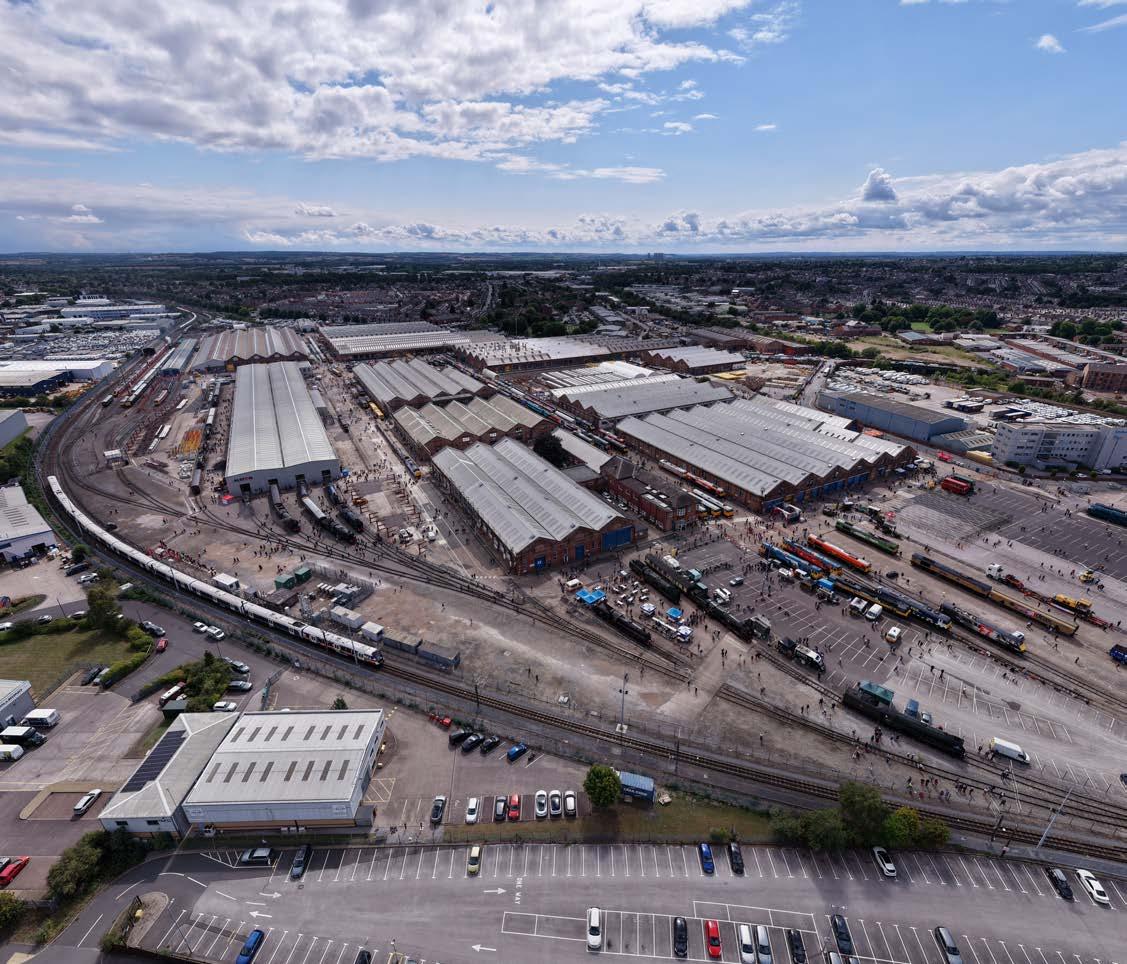
Steam locomotives
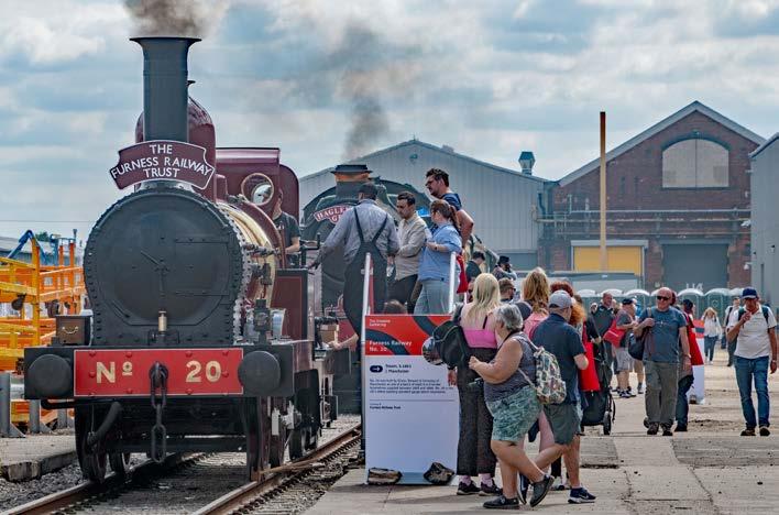
There were over 20 steam locomotives, of which the oldest working locomotive was the 1863 0-4-0 Furness Railway No. 20. After becoming too small for the growth in rail traffic, it was sold to a steel works in 1870 where it remained until it was replaced by diesel traction in 1960. After a time in the grounds of a local primary school, it was purchased for preservation and returned to steam in 1998.
The locomotives on display included main-line express locomotives of the four pre-nationalisation railway companies. Only three of these used 4-6-2 ‘Pacific’ locomotives. The examples on display included a Bullied-designed Merchant Navy class for the Southern, a Gresley-designed A4 class for the East Coast, and a Stanier-designed Princess class for the West Coast. The Collet 4-6-0 designed King class was the most powerful class of locomotive on the Great Western which did not use Pacific locomotives as its express locomotives needed a wide route availability for the branch lines on which they had to operate.
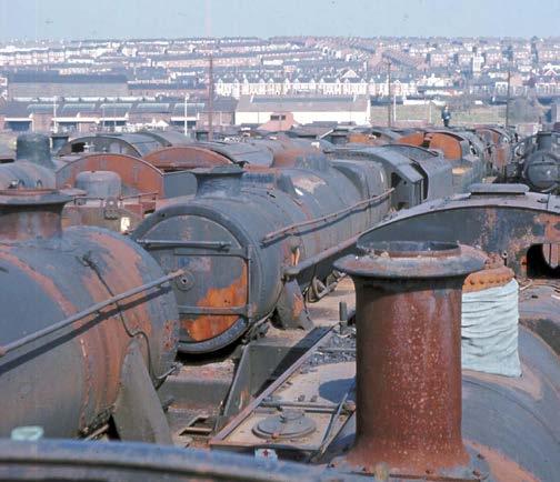
The Class 9F 2-10-0 heavy freight train locomotive, 92214, was amongst the last British Railways built steam locomotives. This was built by the Swindon Works in 1959 and had a short working life of six years. Like many steam locomotives that were later preserved, it was sent to Barry Scrapyard in South Wales after being withdrawn. After being purchased for preservation in 1980 it was finally returned to steam in 2011.
1863 Furness Railway locomotive No 20.
PHOTO: DAVID SHIRRES
(Right) Barry scrapyard in 1969.
PHOTO: DAVID SHIRRES
It is worth noting that the decision of Woodham Brothers to defer scrapping steam locomotives at its Barry scrapyards increased the number of preserved locomotives restored to steam by about 150.
The newest steam locomotive on display was ‘Tornado’, built in 2008 as a modern recreation of a 4-6-2 LNER Peppercorn ‘A1’ class. This locomotive is also pioneering the use of ETCS on a steam locomotive.
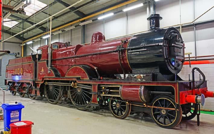
Although it is not possible to detail all the steam locomotives on display, it would be wrong not to mention the one built in Derby. This was 4-4-0 Midland Railway Compound built in 1902, designed by Johnson, and later developed by Deeley. Such compound engines were rare in the UK despite being designed to extract more power from steam. The Midland Compound did this by first expanding steam at a high pressure in a small cylinder inside the locomotive frame and then again at a lower pressure in two larger cylinders outside the frame.
Modern traction
Built at Derby in 1952, Class 08 diesel shunter 13000 was the first of 996 built, making them the most numerous class of UK diesel locomotives. Around 80 of these shunters are still in use today, of which three were on display. One of these, Class 08e 08308 has been converted to battery power.
In addition to seven shunters, no less than 57 main-line diesel locomotives of 29 different classes were on display. The oldest of these registered for main line use was the 1,000 hp Class 20 20007 built at English Electric’s Vulcan works in 1957. The different types of diesel locomotives from the late 1950s and 60s illustrated the wide range of classes produced as part of the 1955 BR modernisation programme, including those with hydraulic transmission.
Some of these 60-plus-year-old locomotives have been rescued from scrapyards and preserved. Others, 20007 and six of the seven Class 37 locomotives on display, have been in continuous use since they were built. The newest diesels on display were two 3,690hp Class 70 locomotives build by General Electric in the USA between 2009 and 2017.
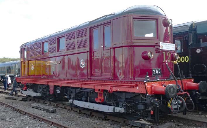
There were 16 electric locomotives on display from 12 different classes. The oldest of these was London Underground’s Bo-Bo locomotive No 12 Sarah Siddons, which was built in 1922 and hauled trains on the Metropolitan line up to 1961. It is now maintained in operational condition for heritage tours.
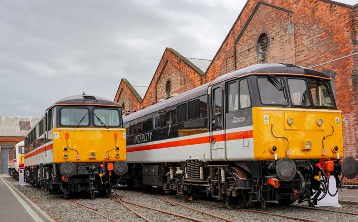
There were five preserved Class 8x locomotives built between 1961 and 1973 for the West Coast Main Line electrification - 87002 was the last of these to be withdrawn in 2006 and is now used for charter work. The Class 91s built for the East Coast Main Line electrification were represented
by 91101 ‘Flying Scotsman.’ This was one of 31 built at Crewe between 1988 and 1991. Only 12 now remain.
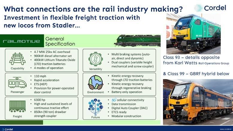
The newest, and most powerful electric locomotive on display was 99001, a Class 99 Co-Co bi-mode locomotive which is currently undergoing testing. When operating as an
(Above) 110 mph Class 87 locomotive.
(Above) Midland Railway Compound.
PHOTO: ALSTOM
PHOTO: ALSTOM
PHOTO: MALCOLM DOBELL
(Above) London Underground's Sarah Siddons.
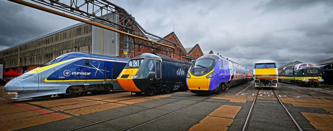
(Above) High speed line up: L to R - 300 km/h
Class 373; 200 km/h HST; 225 km/h (design speed)
Class 390; Class 91 electric loco and Class 55 Deltic locomotive.
electric locomotive it has a power of 6,170 kW. When powered by diesel, its power is 1,790kW.
There was a line-up of high-speed traction comprising of a 300km/h Eurostar Class 373 power car and the 200km/hr UK trains: an Avanti Class 390 Pendolino, a Class 43 HST power car, and a Class 91 locomotive. There was also a 160km/hr Class 55 Deltic locomotive
One item of rolling stock recently built at Derby was the RGX-02 Rail Grinder which was built by Loram UK which has a depot close to Litchurch Lane offering modification, overhaul, and lifeextension services.
Multiple Units
There are only a small number of locomotivehauled passenger trains on today’s railway. Multiple units are generally far more cost effective and offer other advantages, especially at terminal stations. On display were 27 different multiple units comprising of seven diesel units, a hydrogen powered unit, and 19 electric multiple units (EMUs).
Large-scale main line multiple unit operation started with the construction of the first diesel multiple units (DMUs), such as the Class 108 DMU on display. These were built as two, three, or four car units at Litchurch Lane between 1958 and 1961, the last of which was withdrawn from passenger service in 1993. The 333 Class 108 DMU vehicles were part of over 4,000 first generation DMU vehicles produced as part of the 1955 modernisation plan.
Though these first-generation units offered significant cost savings when they were introduced, by the 1980s it was clear there was a need for more reliable units that were cheaper to operate. This resulted in the development of second generation DMUs of which the first were the Class 150 introduced in 1984. On display was a Porterbrook example, number 150231 which was built at York in 1986. The newest DMU on display was a Class 197 assembled by CAF in Wales from 2022 onwards.
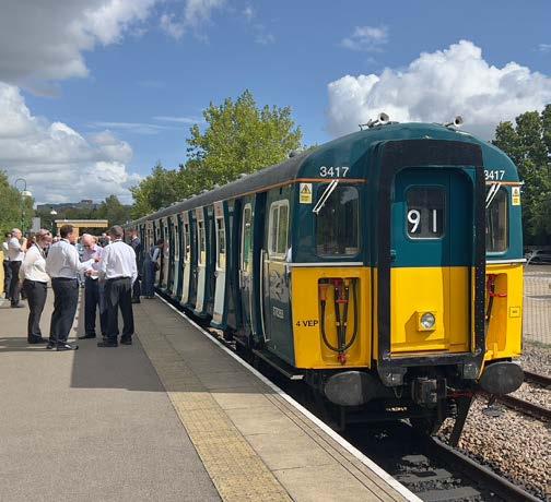
Of the 19 EMUs on display, seven collected DC current from a third rail. These included the oldest EMU on display - a preserved Class 423 VEP Southern DC unit built at York in 1967.
Some consider these units to be ideal commuter units as they have slam-doors at each passenger bay which minimises passenger dwell times. However, this posed a significant safety risk as, at terminal stations, it was not uncommon for many passengers to open the doors and leave the train before it stopped.
The Class 313 units were the first to have both a third rail collector shoe and a 25kV AC pantograph. They were also the first production units derived from British Rail’s prototype suburban EMU design and so had sliding doors. When withdrawn in 2023 they were the oldest main-line units, having entered service in 1976.
Of the eleven 25kV EMUs on display, three were bi-mode units. Two of these were built by Stadler.
The 2018-built Class 755 FLIRT has a short dieselpower car in the middle of the unit while the Class 398 is a tram-train unit that can be powered by batteries. The newest EMU on display was a five-car 25kV Class 730/2 Aventra unit built at Litchurch Lane in 2024.
(Right) Open doors on a Class 423 VEP unit on Bluebell Railway.
PHOTO: DAVID SHIRRES
Train rides
The numerous other attractions on offer included various train rides. These were:
» A trip on a Class 345 Aventra (No 345055) on the works’ 1.4km test track.
» A ride behind steam locomotive 45627 ‘Sierra Leone’ or diesel locomotive 37516 ‘Loch Laidon’ on another part of the works’ track network.
» A cab ride in the tri-mode Class 93 locomotive 93009 which is currently under test.
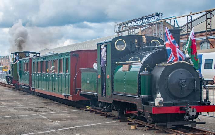
» A two-foot gauge line on which were offered rides on coaches that were ‘top and tailed’ by the world’s oldest operating narrow-gauge locomotive, the Ffestiniog Railway’s 1863-built Prince and Trankil No 4. Both of these locomotives were 0-4-0 saddle tanks. Trankil No 4 was built by Hunslet for a sugar mill in Java in 1971.
» A 15-inch gauge track on which were offered rides behind the 1896-built 0-4-0 saddle tank ‘Katie’ from the Ravenglass and Eskdale Railway.
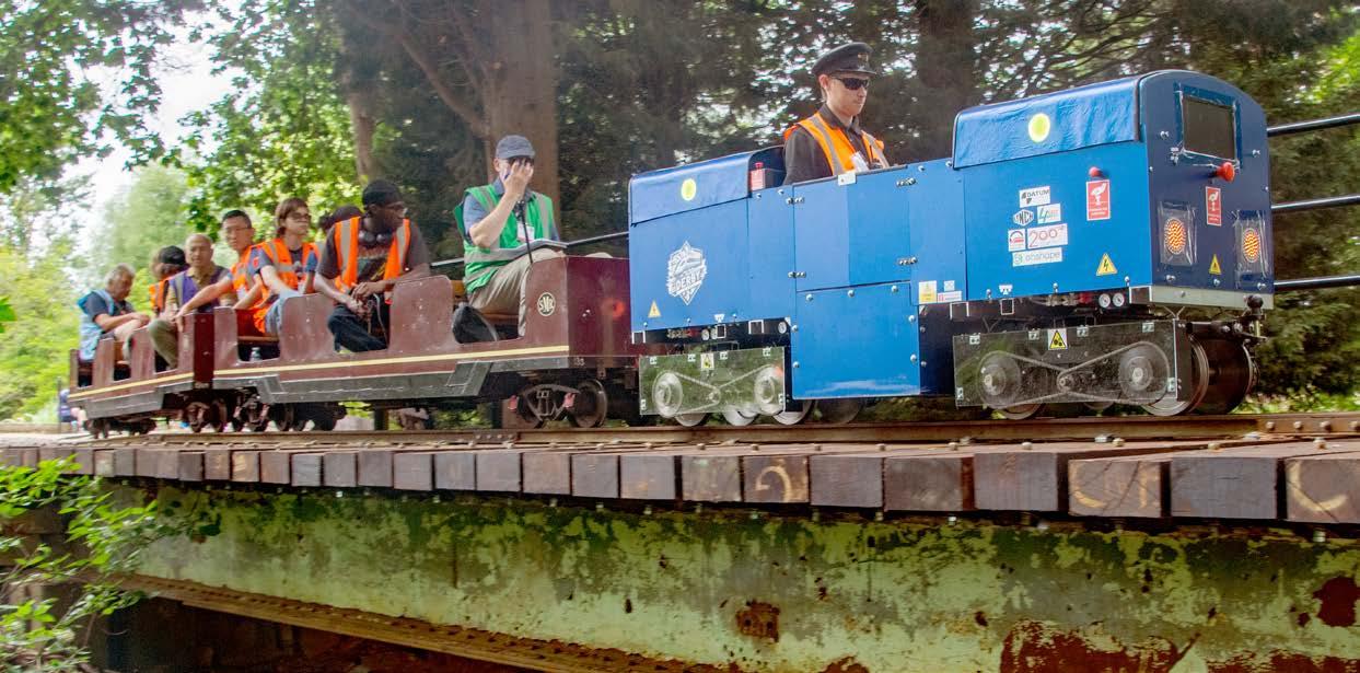
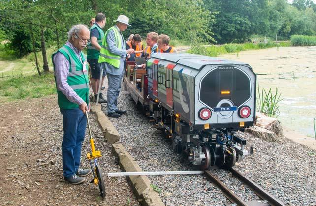
» The 10 ¼-inch gauge locomotives built by the University of Sheffield and a combined Alstom / University of Derby team for the IMechE’s Railway Challenge offered rides on coaches from the Stapleford Miniature Railway where the challenge is held.
» Rides inside one of the workshops behind steam locomotives on a five-inch gauge line provided by the Derby Society of Model and Experimental Engineers.
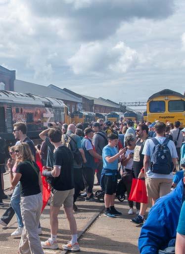
Visitors also had the opportunity to ride on one of the fleet of 22 vintage buses which ferried visitors between the workshops and Derby railway station. Other attractions included live music, street food stalls, family entertainment, and fairground rides. Inside the workshops were an impressive model railway display, a railway marketplace, a heritage and preservation zone, and a ‘meet the railway family’ area. This included organisations such as the Railway Industry Association (RIA) and Chartered Institution of Railway Operators (CIRO).
The modern railway
Though a large part of the gathering celebrated the railway’s past, there was also much to see about the railway’s present and future. The STEM hub showed visitors the Science, Technology, Engineering and Mathematics (STEM) of the modern railway which hopefully inspired some visitors to become future railway engineers. This was hosted by Alstom’s graduates, engineers, and apprentices who demonstrated interactive exhibits such as virtual reality and driving simulators. This also included an exhibition of the history of railway signalling from the first fixed signals in the late 1830s, telegraph signalling in 1850, block signalling in 1873, automatic train control in 1950, computer interlocking (SSI) in 1980, ETCS in 2000, to modular control systems such as Alstom’s MSC-I in 2024.
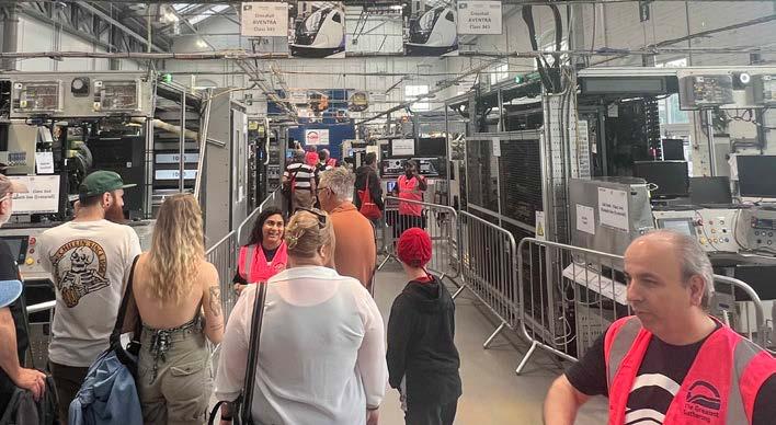
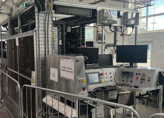
As its name suggests, the Train Zero Delivery (TZD) facility does not build trains. Instead, it is a software test site with static tests rigs of all types of Aventra units. These test rigs simulate the way the train’s software and hardware work together. This enables more thorough testing to be done than is practicable on a train. Hence, this is an essential part of the validation of the train’s design and any subsequent changes. Those visiting TZD could not fail to be amazed by the large volume of electronic equipment on a modern train, which is not obvious to passengers.
(Above) ‘Top and tailed’ ride offered by Prince and Trankil No 4.
PHOTO: DAVID SHIRRES
(Below) Train Zero Delivery.
PHOTO: DAVID SHIRRES
PHOTO: DAVID SHIRRES
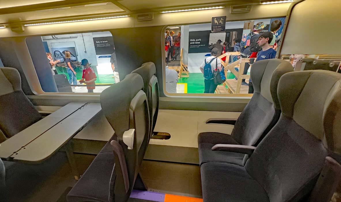
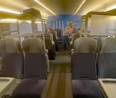
The gathering also provided an opportunity for a sneak preview of the emerging interior train design for the HS2 trains. These will be designated Class 895 and will be partially built at the Litchurch Lane works in a few years’ time as part of a joint venture between Alstom and Hitachi. Visitors were able to go inside full-scale wooden mock-ups of the saloon, catering, and bike and buggy spaces of these new trains.
It was explained that as the mock-ups were built to assess physical layouts they were in white, grey and black. At this stage the design team wished to avoid discussions about colour schemes. Visitors were also advised how these mock-ups had developed after extensive feedback from a wide range of user groups. Despite advances in virtual reality, it was felt that there was no substitute for a full-scale mock up to obtain worthwhile user feedback.
The 200-metre Class 895 units will have 504 seats and spaces for four wheelchairs, four bikes, and two children’s buggies. They will also offer more leg room. Despite this, the Class 895 will have 10% more seats per metre of train than the Avanti Pendolino trains. This will be achieved by placing almost all the train’s equipment below the coach. They will also offer level-boarding at HS2 stations and have a wider step to give an improved boarding at stations on the conventional network.
HS2’s trains will also have bio-reactor toilets that separate and treat waste on board which allows discharge to specialised station drains to extend toilet servicing from once every few days to once monthly.
Back to normal
Setting up the workshops for the gathering was no mean feat, though this was made possible by the two weeks beforehand being the works maintenance shutdown period. Although Alstom and its 350 volunteers deserve great credit for making this event happen, many other railway companies and organisations did a great deal to make it a success.
It is ironic that the gathering was only possible due the hiatus caused by the gap in train orders. For this reason, it is probably true to say that though Alstom is rightly proud to have hosted such a huge event, it doesn’t want to be in a position to do so again.
After the last visitors left, the job of getting the workshops back in business began. This was helped by half the workshop space being closed to the public during the gathering. It also required numerous train movements from the workshops which included trains with five diesel locomotives and four steam locomotives.
And so it was that, less than a day after hosting a once-in-a-generation celebration of the heritage and future of Britain’s railway, the Litchurch Lane workshops started producing its order for additional Elizabeth line trains. After seeing the scale and capability of this facility at the gathering, it is difficult to imagine that it would have closed had it not been for this order.
PHOTO: DAVID
PHOTO: DAVID SHIRRES
MyPeople Group:
CHRISTIAN HUGHES
Safety is a priority for countless industries, none more so than rail. However, it remains a weak spot for many organisations, and the challenge boils down to human behaviour. Every workforce is a mix of motivations, skills, values, team dynamics, and behaviours, and it’s this human complexity that makes safety both essential and fragile.
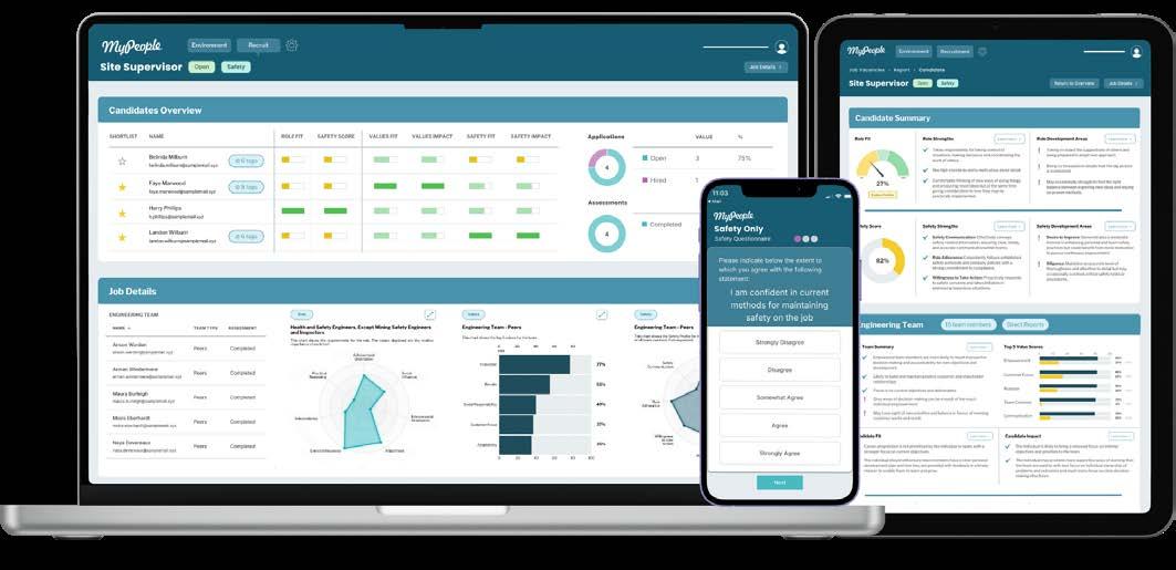
Software firm MyPeople offers behavioural talent intelligence solutions that transform how organisations hire, develop, and manage high-performing teams. The company is currently lending its expertise to the rail industry, with which it is working to improve safety culture across the network.
Rail Engineer sat down with MyPeople Chief Executive Officer Christian Hughes to discuss the challenge facing the industry and the solution his company provides. He began by explaining how his previous role in sports psychology informs his current work.
“With a background in psychology and data, the first 10 years of my career were spent working in elite sport with teams from British Olympic Cycling, Saracens, and England Rugby.
TRANSFORMING SAFETY CULTURES
“The work that we were doing was about understanding the dynamics of teams and how teams influence an individual’s performance. We wanted to understand this from the performance perspective of elite cyclists, examining our development processes and training programmes to assess their effectiveness in improving athlete performance. We found many marginal gains that contributed to a very successful period - not just for British Cycling, but for all of these teams.
In 2014, after working in the business world and with private equity firms on productivity measures, Christian and his team developed their MyPeople software product. The crux of the company’s work
is to help large organisations understand the effectiveness of their training and development programmes, and to address behavioural and hiring challenges.
“The MyPeople platform enables businesses to select and profile individuals and, fundamentally, it tells them whether particular candidates will be able to work within their team safely and effectively.
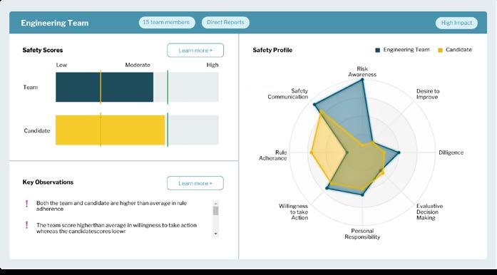
“Over the last two years, we've expanded our approach to model the behavioural safety of teams and we now work in many safety-critical industries with customers like Network Rail, where we help them understand how specific behaviours contribute to safe and effective team actions on the railway.
Evaluating competence
In the past, says Christian, much like in sport, competence was defined as having the right skills and therefore, it became something of a ‘tick box’ exercise. What we have found is that behaviours of individuals and teams underpin safe performance and so need to be measured and evaluated too. Most accident reports list human factors like communication and situational awareness as contributing factors to incidents.
That said, Christian is quick to praise the rail industry’s work around safety. Indeed, today’s employees are encouraged to speak out and report any safety incidents they might experience or witness. However, this can lead to an increase in incident reports and, at times, new processes being put in place that don’t address the core challenge.
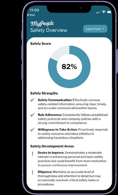
“Our hypothesis is this is a behavioural issue,” says Christian. “For example, we’ve found that how people speak up about incidents and whether they take action is nuanced by individual personality and the working culture of particular teams. Interestingly, we’ve also found that there are different patterns of safety-related behaviour in different rail regions.
“For example, you may see differences between attitudes to problem solving, confidence in skills, rule adherence, and willingness to act that vary by role and by region. These differences influence how safety briefings are delivered and how onsite safety is managed.”
These regional differences highlight why a one-size-fits-all approach to behavioural safety is limited – which is where MyPeople’s profiling tools come in.
Providing solutions
To help the industry meet this challenge, MyPeople has developed a suite of three core safety profiling products.
“The first is our Safety Culture Evaluation tool, which measures the interplay between people, values, and workplace environments to foster a strong, sustainable safety culture.
“By applying behavioural safety insights and cultural transformation strategies, we help organisations to embed safety as a core organisational value. Our datadriven approach helps businesses to make evidence-based decisions, creating safer and more resilient workplaces.
“Our Safety Hiring tool enables organisations to recruit individuals with the right safety mindset and behaviours. By integrating predictive analytics with behavioural insights, we help businesses identify candidates whose values and risk awareness align with a strong safety culture.
“Finally, our Safety Development product helps individuals and teams build the habits, accountability, and mindset needed for continuous safety performance. The tool provides group-level analysis to balance team strengths, clear coaching actions to support change, and tracks behavioural progress over time to sustain improvement.”
The advantages of MyPeople’s approach are evident. Organisations gain vital insight into their behavioural risk profile, allowing them to deliver training that builds a common understanding of safe working practices and, ultimately, a safer workforce.
For job candidates, it provides clarity on the behaviours expected of them and highlights any personal biases they
may need to manage. On site, the same data can guide targeted interventions and shape more meaningful safety briefings.
Shifting safety cultures
Safety in rail has always been about more than processes, checklists, and technical competence. It is shaped by people and their behaviours, values, and decisions under pressure. MyPeople’s behavioural intelligence tools shine a light on this human dimension, helping organisations such as Network Rail better understand the factors that drive safety outcomes.
By embedding behavioural insights into hiring, training, and everyday practice, rail companies can move beyond compliance to build a culture where safe behaviour becomes second nature.
In a sector where even the smallest oversight can have far-reaching consequences, that cultural shift could prove to be one of the most important safeguards of all.
A ONE-STOP SHOP FOR OLE INSTALLATION
Gripple SwiftLine: E
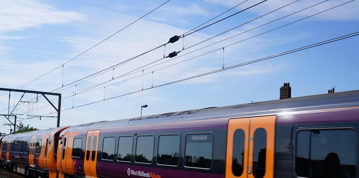
lectrification – it’s the subject on every rail professional’s mind and a key priority for the rail industry as it drives towards a greener, more sustainable future. But the pressure of tight possession windows, maintaining safety at height, the skills shortage, and the demand for continuous accuracy are significant challenges for any electrification programme.
Currently, the UK lags behind its European neighbours, with just 38% of its track electrified, compared to the continent’s average of 60%. More than ever, we need to simplify the traditionally complex processes – without compromising quality or safety. This is not just a niceto-have; it’s a necessity to ensure the UK’s rail provision keeps pace with the rest of the world.
Network Rail has called upon companies to innovate to stay at the forefront of the challenge and Gripple, the Sheffield-based manufacturer, has responded with a range of fast, simple, and efficient OLE solutions. With overhead lines at the core of electrification, Gripple is determined to provide engineers with the solutions they need to unlock further rollout.
To gain insight on the impact Gripple is making in the rail sector, we spoke with Group Business Development Director Glenn Bills and Group Product
Manager Paul Whittle about Gripple’s SwiftLine range – the industry’s key to achieving full rail electrification.
Making tracks
Having been around for more than 30 years, Gripple initially made its name as the original inventor of wire joiners and tensioners. The company has since expanded its product range across diverse sectors, including building services, agriculture, civil construction, landscaping, utilities, solar solutions, and more recently, the rail industry.
“Through the decades, Gripple’s guiding mission has been to create simple solutions that make a real difference –saving the installer time,” says Glenn. “It’s this commitment to problem-solving that propelled us into the rail sector. After many discussions with engineers and contractors, we were able to identify the industry’s struggles
and address them with the launch of our inaugural rail product, SwiftLine Rail Dropper, back in 2023.”
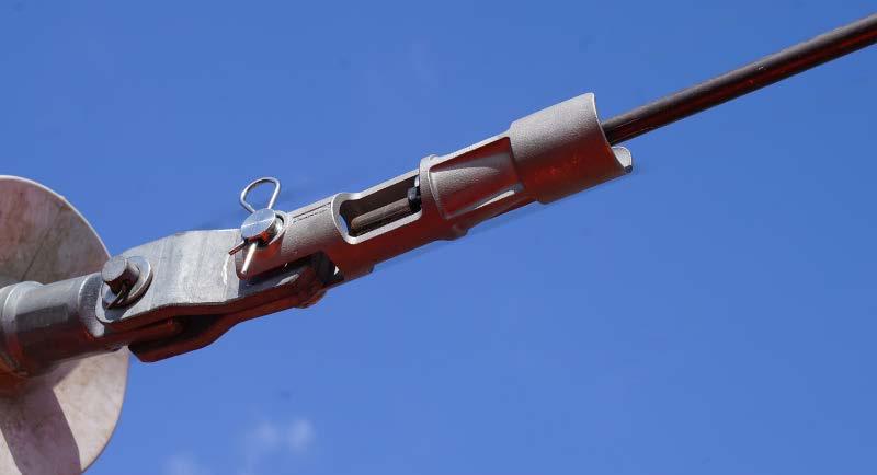
Gripple’s SwiftLine Rail Dropper provides a fast, efficient alternative to traditional OLE droppers. Designed for quick and easy installation, its simple but secure quarter-turn catenary fixing and the auto torque contact wire clamp ensures the correct torque every time and best-in-class cable protection. It hangs vertically to connect the catenary and contact wires at regular intervals, ensuring uninterrupted conductivity.
But Gripple didn't stop there. In 2024, it introduced the SwiftLine Rail Jumper, enabling OLE engineers to attach to the catenary and contact wire in seconds. Thanks to its toolfree auto torque clamps with V-spring fixings, it is significantly faster and easier to install than traditional parallel groove clamps – and built to be four times longer lasting.
“These solutions were created with the aim of removing complexities on site,” explains Paul. “The pre-assembled and adjustable nature means far more can be done within a
Glenn Bills.
Paul Whittle.
possession window, all while reducing the time spent working at height and in the dark.”
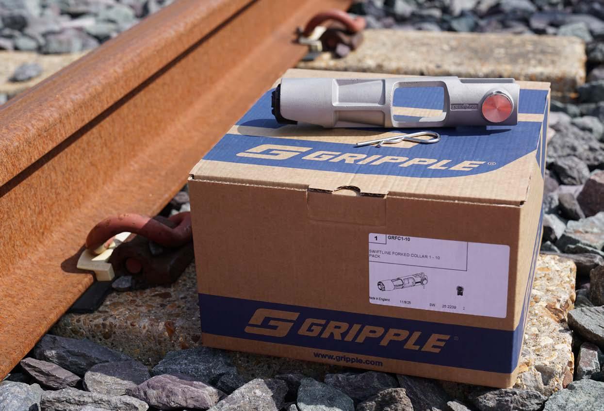
The latest innovation
Launched this spring, the SwiftLine Forked Collar is the latest addition to the SwiftLine range.
Glenn outlines how things have worked until now: “Forked collars, used for terminating and connecting the ends of conductor wires on OLE, are typically hindered by complex installation processes. The lack of a universal design has made them susceptible to user error which can lead to increased safety risks and costly project delays.
“Until very recently, collars have relied on a cone-shaped gripping mechanism which doesn’t allow the wire to return once it has been pushed through. Even the most minute of mistakes can mean wasted materials and time – and starting again from scratch. That’s not a luxury most teams have, especially with tight possession windows where delays can run up fines in the tens of thousands.”
Paul warns: “Forked collars may be seen as a small component, but they bear a disproportionate amount of risk if it goes wrong. That’s why the SwiftLine Forked Collar is a game-changer. It means tool-free installation, universal cable compatibility, and, crucially, adjustability. So, if something isn’t quite right, it can be corrected easily, without being torn down and reinstalled.
“Another handy feature is that inspection windows allow engineers to check installations from ground-level, and a noweld design improves product durability in those more challenging rail environments. Plus, contractors can shorten project timeframes with faster installation, making them more competitive by reducing labour costs.”
The SwiftLine Forked Collar recently gained coveted Network Rail approval. “It’s the ultimate seal of approval, and this marks the third product in the SwiftLine range to receive such an endorsement,” beams Glenn.
But while this is a significant milestone for Gripple and a step forward for the industry, let’s take a look at the wider picture…
The SwiftLine range
Paul explains: “With the Forked Collar joining our existing SwiftLine Rail Dropper and SwiftLine Rail Jumper, we now offer a fully integrated suite of products providing OLE engineers with everything they need to simplify workflows, boost safety, save time and money, and meet the ultimate goal: accelerating rail electrification efforts.
“Gripple is proud to be the only manufacturer offering a complete, startto-end solution for OLE installation,” adds Glenn. “While there’s no shortage of players in the industry, there has been a lack of cohesive solutions where all products work together seamlessly and are available from one trusted supplier – especially one who is UK-based, manufacturing all components in-house.”
Designed with OLE engineers in mind
“Each SwiftLine product has been meticulously designed in consultation with OLE engineers who are out in the field every day battling time pressures, tight budgets, and unpredictable weather conditions,” explains Paul.
“From speaking with engineers, project managers, and rail teams across the country, it’s clear there is a strong appetite for change – but only if that change makes things genuinely easier on site. They want and need straightforward answers to complex problems.
“In a typical installation, engineers often juggle several tools, adjusters, and fixing systems that don’t always integrate smoothly. That means more time on site and more room for error. But the SwiftLine range offers engineers a cohesive system. This is what’s needed to deliver projects efficiently, safely, and to a high standard.”
“What sets our solutions apart are their universal compatibility and toolfree installation, ensuring streamlined installation on every project, every time,” shares Glenn. “Due to its ease of use, minimal training is required, so even when skills gaps and labour shortages arise, projects won’t need to come to a halt.”
Real-world impact
The SwiftLine range is already having a huge impact on electrification projects across the UK.
One such example is Busby Junction in Glasgow where the team faced a tight 72hour possession window to replace droppers and adjust the catenary height. Using traditional methods, this would have been a complex, timeconsuming process. Gripple’s SwiftLine Rail Dropper enabled the team to complete the installation quickly, even in cold and wet conditions, eliminating the need for cutting, crimping, or on site fixes. Its pre-assembled, fully adjustable design meant the team could adapt the droppers to the as-built track position with ease. Furthermore, the quarterturn catenary fixing and auto torque contact wire clamp ensured accuracy and consistency, eliminating installation errors. Alan Kennedy, head of engineering at SPL Powerlines, described SwiftLine Rail Dropper as a “real game-changer” in terms of ease of use and safety.
Similarly, while working alongside REL, which forms a part of the QTS Group, and Network Rail, Gripple supported the delivery of a successful structure repair in Tamworth. With tight deadlines to avoid train delays, the installation team didn’t get chance to take exact measurements of the droppers before the job. That’s where SwiftLine Rail Dropper really proved its worth as its adjustability made the installation quick and hasslefree.
Ross Dickson, OLE project manager at QTS Group, commented on the project: “Had we not had flexibility in the droppers, we would need to renew the droppers on the final shift, which ultimately could have ended in the first train being delayed.”
Sustainability in rail
“Beyond the more obvious benefits like safety and efficiency, our SwiftLine range supports long-term sustainability goals too,” remarks Paul. “The push for full electrification by 2050 goes hand-in-hand with the drive to reach net zero. That’s why all SwiftLine products are fully
adjustable and reusable. They can be relocated and reinstalled without the need for new materials, helping reduce waste and costs while aligning with sustainability initiatives.
The industry’s future “Gripple’s role goes beyond just manufacturing and supplying components,” Glenn notes. “It’s about being an active part of the rail evolution in the UK and globally. Our SwiftLine range can make a real difference in the industry; taking the time, cost, and stress out of OLE installation for the engineers out in the field.”
Paul concludes: “There’s still a lot of ground to cover to reach 2050 electrification targets. But, as the only supplier offering a fully integrated, Network Railapproved system for OLE, we’re proud to support engineers in delivering their work faster, more safely, and with fewer unknowns, ultimately shaping the future of rail.”
For more information visit: www.gripple.com/rail
Connecting the UK rail industry for over 28 years.
ETCS Implementation issues
Rail Engineer has devoted many column inches to ETCS but mostly about its cost and deployment issues. ETCS is much more than a signalling system as it requires information about train formation, loads, and other characteristics. Inevitably, for a new system, some of these requirements might conflict with current national practice. It has been suggested that national practice should be changed in order to deliver the benefits of the inter-operable system. However, this is easier said than done, and resolving these issues takes time and money which is one reason why the first installations might cost more than the production run.
Some of those issues discussed here, if not addressed, could hamper operation of some types of train and could lead to some classes of locomotive being prohibited altogether.
Partly this is as a result of Great Britain’s flexibility in what vehicles it allows to run where and partly because important aspects of GB practice were not incorporated into the standards/ specifications. The risk is that lowest common denominator default values could be used, leading to a significant reduction
in network capacity compared with the current lineside signalled railway with its rules and signage.
Rail Engineer understands that a paper outlining the issues was presented to the Office of Rail and Road (ORR) in early 2019. These are system issues that need to be captured in ETCS but cannot be resolved by signalling engineers alone.
Network Rail and the ORR were asked for comment. Network Rail gave some useful feedback which is reproduced in full.
The issues are:
» Braking values for various train formations.
» Axle load categorisation for bridge loading.
» Implementation of differential speed limits.
» Cant deficiency rounding.
Braking values
ETCS onboard equipment needs to know the braking capability of each train. There are two means of entering braking data into the ETCS Driver Machine Interface (DMI).
The first, Gamma, is a series of data generally applicable to fixed formation trains. The data is pre-loaded into the onboard equipment, and the driver selects (or the train could select automatically) based on the formation, e.g., four-car, eight-car. For GB application, Gamma is the proposed braking data format for multiple units (MU).
MALCOLM DOBELL
However, for most existing GB MUs, the required Gamma data is not held on the industry database known as R2 and will need to be determined from design data/ test train results. More recent MUs should have the Gamma value supplied by the manufacturer.
The other method is called Lambda. This is used to define braking capability for loco-hauled trains, both passenger and freight. The problem here is that the braking performance of GB domestic vehicles is not assessed against the UIC Leaflet 544-1: instead, Railway Group Standard GMRT2045 is used. As a result, R2 does not hold the ‘Brake Weight’ values required to determine the Lambda value. Even if R2 did hold the right information, TOPS (one of the oldest computer systems still in front line use) does not have the functionality to generate the correct Lambda value applicable to a particular train formation, for the driver to enter into the ETCS DMI.
Early proposals were to use a default Lambda value for all freight trains irrespective of actual formation/braking capability. This would inevitably slow the trains and consequently reduce the number of available paths.
Network Rail agreed with the above assessment and reported that:
“The sheer magnitude of variation outside of fixed formation MUs is something that ECDP and the wider community in the UK has recognised. Since the start of the decade the programme has been looking at this issue and the need for a robust and safe mechanism to input the data into the DMI and forms part of the Train Data Entry project.
“This is now well developed and will initially require a manual check of data, but progress is being made on using an app-based solution to provide the data to the driver. The use of a ‘Consisting app’ is
already part of the freight scene in the UK and the mathematics to draw data from R2 to populate this activity is understood. R2 is not in all cases up to date, but for the vast majority of more modern wagons, this is an admin task from available data. For some older types, or those where no operational need pertains, a default value can be used. Similarly, for heritage operations there is not as much variety as in the freight space meaning a similar solution, possible a simplified version, will also be effective.
“This provision will enable optimisation of train performance and pathway allocation as ETCS rolls out across the network. ECDP as the pioneering programme recognises that until we have various OEM fitments, operating companies and train types in use on ECML, the full optimisation will not be possible. A key phase of development is that theoretically important calculations and standards are then optimised on the real railway to ensure that the full benefits of ETCS are delivered.”
Axle load categorisation
ETCS uses load categories as defined in EN15528 Railway applications - Line categories for managing the interface between load limits of vehicles and infrastructure. This does not map directly to the route availability (RA) categories used in GB. It is relatively straightforward to determine the EN 15528 load category for a train but is said to be a 20-year task to re-assess all structures (viaducts, bridges, culverts etc., on all lines, although it is understood that this task has started. Simplistic conversion can lead to permission to operate over tracks not currently permitted and vice versa.
GB has permission in the Infrastructure TSI (now NTSN) to continue using the RA method for assessment of compatibility for trains and infrastructure, but this
permission was not included in the Command and Control System TSI. Thus all axle load related information used within ERTMS is categorised according to the EN15528 load categories and drivers are required to enter the EN15528 load category of the train during data entry. As well as axle-load-related speed restrictions, the ERTMS route suitability function includes axle load as one of the factors against which route compatibility is assessed. This is again defined according to the EN15528 values. Therefore, until the infrastructure is re-assessed, this element of the ERTMS route suitability functionality will not be available for use in GB.
It is expected that a marginal additional cost would be incurred if structures are re-assessed to EN15528 as well as RA capability as part of the existing assessment schedules (hence the 20-year timeline). However, these assessment schedules are unlikely to match the ERTMS implementation schedule. There are potentially large cost, resource, and schedule implications if the structures have to be re-assessed outside the current scheduled structure assessments.
It should also be noted that the EN15528 method is not suited to some GB vehicle types, such as three-axle bogie locomotives (i.e., classes 37, 56, 60, 66, 69, 70, 92, and 99, and various heritage locomotives) whose capability could be dramatically reduced if the EN system is directly applied.
Network Rail reported that:
“The alignment of European categories to traditional UK Route Availability categories has been perceived as more difficult over recent times, but the strategy now being developed is to use the axle weight categories in the ETCS system as planned and link this data to RA categories. The trackside speed curves within the RBC will reflect the RA speed
curves and therefore if the RA category is entered on the onboard system by the driver, then the appropriate RA speed curve in the RBC will be selected. There will then be a translation of RA to axle weight category available to the driver (lookup table initially and potentially input directly) so that each consist can have the appropriate RA curve.
“This minor adjustment is in development and would avoid a major change to bridge assessments and any loss of capability by various vehicle types.
“In the interim, traditional RT3973 forms [Advice to Train Crews - Conveyance of Exceptional Loads] will still be used for this as the development continues to automate parts of the process and provide the protection inbuilt in ETCS and will continue to be used for other operational purposes.”
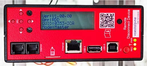
For readers unfamiliar with the term RBC, this is the Radio Block Centre which is a trackside device for a particular section of track which holds infrastructure data such as trackside speed curves. It also communicates with interlocking and then uses all this information to issue trains with a movement authority via the GSM-R radio.
Rail Engineer understands that Network Rail's statement above represents a transitional solution suitable for use on ECDP and potentially nationally, while a permanent solution is developed for national use. In addition, Network Rail is well aware of the potential conflict between the assessment method for EN15528 and its impact on use of three-axle bogie locomotives on certain structures and is developing a solution that will, at least, maintain current capacity.
Differential speed limits
Currently many lines have several differential speed limits. For example, parts of the West Coast Main Line fast tracks have three: 125mph for tilting trains fitted with Tilt Authorisation and Speed Supervision; 110mph for non-tilt multiple units capable of this speed; and 100mph for everything else. There are other examples applicable to certain types of train operating in certain places.
These categories are not catered for in ETCS so the default position would be for all trains to run at the lowest of the signed speeds at any location, with a significant reduction in capacity and adverse effects on journey times and rolling stock utilisation.
There have been proposals to deal with this issue. In summary, ETCS trackside would send a speed profile to the train
which may consist of one or multiple speeds at any location. Where more than one speed is sent, each speed would be tagged effectively with the types of train that could use that speed. Each train type would have a set of data pre-programmed which the on-board uses to select the appropriate speed profiles which apply to it at any location, with the default value being the lowest if in doubt or in the absence of any other data. The ETCS system has limited criteria for differential speeds so some of the current GB flexibility cannot be included in this way.
ETCS does allow for the definition of different speeds depending on various train properties. This includes specified cant deficiency categories (see panel). However, the values defined for ETCS omit the GB values: 75mm (mainly freight; 90mm (some freight but mainly passenger); 110mm (passenger);185mm and 265mm (tilting trains). The default response would be to round down the cant deficiency value leading to a speed reduction of 2mph to 5mph, further impacting on journey time/capacity. The alternative would be to move up to the next higher cant deficiency value. While some of the speed increases could probably be accommodated safely by vehicles, any speed increase at a specific location would require the gauge clearance for all vehicles to be checked which might identify gauge infringements or additional inspection requirements. The speed reductions involved are quite small but could apply at many locations and the impact of these variations would need to be evaluated by modelling, but it’s just another factor that might slow trains.
Network Rail reported that:
“ECDP’s initial deployment for the training and migration phase will not include differential speed capability. This
is being managed to avoid restrictive operational issues by Network Rail as an interim measure. From the first signals away area on ECDP (Biggleswade to Fletton), just a few years away, differential speeds for permanent speed restrictions, temporary speed restrictions, and emergency speed restrictions will be provided by an upgrade of the RBC capability.
“That functionality will then be retrofitted to the migration area from Welwyn to Hitchin in due course. As we look to deploy ETCS more widely, the key consideration during design for differential speeds will be in understanding the purpose of the restriction and matching the profile as closely as possible to one of the applicable ETCS categories and assessing the impact of any change from today’s working in so doing.”
Conclusion
It is good to see that ECDP recognises the issues and has ways of dealing with some of them, but it does highlight that the implementation of ETCS –fundamentally a speed signalling system compared with UK’s current route signalling approach – impacts on a lot more than is usually covered by signalling design. This is a business change programme that fundamentally affects how train drivers work.
In particular, freight train drivers have to enter data into the system, representing a risk of incorrect data entry. It is good to see that ECDP recognises this risk and acknowledges the need for “a robust and safe mechanism to input the data into the Driver Machine Interface (DMI)”.
As Network Rail acknowledges, there are still issues to resolve and no doubt Rail Engineer will return to this topic.
Cant deficiency refers to the difference between the actual cant (or superelevation) of the track and the ideal cant needed to balance the centrifugal force of a train traveling through a curve at a specific speed. When a train travels faster than the speed for which the cant is designed, it experiences a cant deficiency, meaning the track is not tilted enough to counter the centrifugal force, leading to a lateral force pushing the train outwards. Trains are designed and approved for particular maximum cant deficiency values, depending on their intended operation.
PHOTO:
ETCS
DISRUPTIVE TECHNOLOGY FOR RAILWAYS
These days we are often encouraged to think disruptively. The phrase is used to suggest that if we change the way we do things we will get better products and processes, often at lower cost. Is moving to European Train Control System (ETCS) one such example?
Moving from a lineside signalling system to an in-cab control system is certainly a big change. It is potentially disruptive to several areas of railway operation and engineering and therefore needs to be approached carefully to ensure it is completed successfully. It also has the potential to bring several substantial benefits to the railway.
Constraints of lineside signals
There are three fundamental constraints arising from lineside signals.
The first is that signals are in fixed positions. Since all train drivers must have time to read the message a signal is giving and then control the train appropriately, the distance between signals must be adequate to manage the train with the longest braking distance. This generates a fundamental compromise on signalling scheme design on a mixed traffic railway.
The second is the need to understand the human factors issues that may influence a driver’s response to a signal. Because of the nature of a train, responding to a misunderstanding will occasionally come too late to prevent an incident or, in the worst case, an accident. Thus, it becomes critical to ensure the meaning of a particular signal is clearly understood so the right response occurs.
Signals are therefore placed in clearly visible locations, at approximately equal intervals, and on multiple track railways in parallel locations in an attempt to ensure the correct signal is read. There is also the constraint of how many different aspects a signal can display which is, to some extent, limited by colours that can be easily distinguished several hundred metres away. Indeed, most railways also have systems to ensure the driver has their attention drawn to an approaching signal, and sometimes speed limits. In Britain it is the Automatic Warning System (AWS) system.
Finally, because signalling equipment is distributed widely across the network, power and communications equipment need to be provided to enable the equipment to function. This adds both capital cost in its provision and ongoing service costs keeping it maintained and functional.
It can therefore be seen that while lineside railway signalling is fundamentally about allowing trains to move safely across the network, there are several constraining factors that add cost and deliver a suboptimal result.
Some of these constraints, especially those related to human factors, could be ameliorated by the use of a comprehensive Automatic Train Protection (ATP) system. If, however, lineside signals are retained it becomes just another added element of the system with further failure risk and very limited benefit other than improved safety. Remember, train safety on the railway - at least in Britain - is already very good.
DAVID FENNER
Cab signalling
Using cab signalling, where the train knows its own braking performance, removes the first compromise. The infrastructure now only needs to tell the train the location at which it must stop. The train then informs the driver when its speed reaches the braking zone and, should the driver fail to react, the ATP function cuts in and initiates the brake response. Thus, compromises on maximum speed and interval between signals are removed. So are the constraints around signal aspects meaning in a few places, especially converging junctions, a joining train can be allowed to start much sooner after another train has passed.
In addition, with cab signalling constantly advising the driver of the maximum safe speed for that train, the human factors issues associated with lineside signals are much reduced. That is not to say there are no new human factors challenges to be considered, but with the support of ATP many of them are of a very different form.
Because there is only a need to inform the train of the stopping location the amount of lineside equipment can be substantially reduced. On mainlines with frequent traffic, section lengths may not change very much because of the need to keep following trains moving. On less densely used lines the normal signal spacing could be changed to suit the headway requirements, or those required to meet operational recovery needs, and on rural routes only the essential stopping places need to have any equipment at all. This is especially true with axle counterbased train detection.
With that background let us discuss the challenges and opportunities in more detail.
Challenges
The first challenge is train fitment, closely followed by driver training.
To be able to remove lineside signals, every train permitted to run along the route in open traffic, i.e. not under possession, must be fitted. Many railway assets are long lived, and this especially applies to rolling stock. Until a cab signalling system becomes universal there will inevitably be vehicles that need retrofitment.
This is a multi-dimensional problem:
» Where will the equipment be fitted? Does that comply with all the system design criteria such as distance from the front end?
» Can the drivers desk be modified such that the driver can see and use the new cab display in all likely lighting conditions?
» The cab signalling system needs to know position and speed at any instance. Are suitable interfaces to tachometry systems available or can they be made available?
» Where can the necessary radio communications equipment and antenna be mounted? (Although with all trains now required to have a radio this is a relatively small problem.)
» How will the interface to the braking system for the ATP function be implemented?
» What disturbance to existing equipment is likely to facilitate this installation?
» Those are just the technical questions. What about the commercial concerns of a vehicle being out of service? How long? What post fitment testing is required? Will reliability be impacted?
It is hardly surprising that retro-fitment costs are extremely high. Unsurprisingly, the trend is to a first of class fitment
model to iron out the fitment arrangement and prove a satisfactory result before rolling the fitment across similar vehicles. That may not be the end of the challenge because, as we know, vehicles of the same class are not necessarily identical especially if they have a few years life under their belt. But once cab signalling is the standard fitment at build, it is both a relatively marginal cost compared to a new locomotive, even more so for a multiple unit train, and will be in a competitive marketplace compared to retro-fitment which has a very limited market place for each type of vehicle.
At the top of the operating tree is driver training. This is a substantial change to a driver’s normal working environment. Instead of looking for signals they are now required to monitor a display in the cab and respond to the prompts it provides while still keeping a close eye on the outside world for conditions or events that are not reflected in the signalling system –trespassers and trees come to mind. But here we also need to factor in frequency of use. The training can only be done when a driver is likely to use the new skill, otherwise that skill will be degraded or even lost.
However, that is not the only operational change that is created. How do platform staff know the train is able to proceed and thus the doors need to be closed? There is no proceed signal at the end of the platform. Even deeper into the operating organisation, and with reference to the earlier comment, there will be a change to how operators decide the signalling scheme design they need. Does this require a new or at least changed skill set to define the real operating parameters for the line?
We can then move on to rolling stock engineers who will need to diagnose and fix any faults with new and complex equipment. But even before that happens, how do we define the brake performance of a train and what safety margins are we going to employ? Do we have suitable current data available, or do we need to reorganise our braking models? Our accompanying feature “ETCS Implementation issues” explains how a train’s braking curve is input into the ETCS system and the issues associated with doing that for freight and other locomotive-hauled trains.
No easy solution
This is a double-edged problem because we need to define both a service brake performance and an ‘emergency’ brake performance and, if the latter takes longer to stop the train than that of the service brake, it will dominate and cause both human factors and operational challenges. This is especially a challenge for mixed formation trains such as freight or charter traffic. It also challenges the definition of an emergency brake as the one with the shortest stopping distance is not necessarily the one that is ultimately most reliable.
The signal engineer also has some major changes to consider and resolve. Fundamentally much of the signalling becomes ensuring a safe route is properly set for each train and that there are no or extremely limited opportunities for another vehicle to make an incursion into that route. But they also need to ensure complete details about the topography of the route, especially gradients, and that permitted speeds on every section of the route for each class of train are captured and stored, ready for transmission to the train as part of the movement authority. There is also likely to be a need to relearn
the optimal sectional layout to achieve the desired headway for the traffic proposed on that route.
We then come to the electrification engineer. He gets one major benefit in not being required to consider signal sighting when positioning OHL equipment. The compensation is much more discussion to ensure stopping locations do not end up with the train gapped (on third rail) or being too close to a neutral or isolating section on overhead line.
The other feature of early implementations of ETCS is the testing. The current testing regime is proving very disruptive to railway operation. Better testing regimes are possible but one needs to gain confidence they are secure and suitable. Perhaps the initial disruption is understandable given the implications for safe travel if something is wrong.
While this is only a partial list, it illustrates that moving to a cab signalling system such as ETCS can be disruptive and we need to understand these challenges early in any roll out of the system.
Benefits
Having highlighted some of the reasons why it is so challenging to get ETCS functional on the railway we do need to appreciate the opportunities it brings.
The first and major benefit is it releases signalling or train control system design from the constraints of colour light signals on posts beside the railway. There is no longer a need to place signals according to restrictive standards that are there to ensure drivers know exactly how to react to the aspect being displayed. Sections can be much shorter where this provides a benefit such as at converging junctions or on approach to stations where occasional trains stop such as Stevenage or Grantham. Similarly, on multi-track sections of line would there be benefit having different stopping points to suit the dominant traffic?
There is of course a significant cost saving in not providing the signal and associated support structure or a power feed and interface to the interlocking. The absence of much lineside equipment will simplify ongoing maintenance, and
PHOTO: NETWORK RAIL
should significantly reduce the failure rate and speed up return to service because of reduced travel time.
The signalling interlocking is significantly simplified because it fundamentally only needs to provide a proven safe path for the train. It no longer needs the logic to prove a suitable aspect is displayed on the signal and especially does not need the logic to manage junction signal aspect release as practiced in the UK. Aspect release at junctions has developed following overspeed incidents through divergent junctions and is essentially addressing a human factors problem but recent events, such as Spital Junction and Grantham to mention just two, show this is far from secure. Such overspeed events will be managed by ETCS and it will also enable emergency speed restrictions to be quickly applied without staff needing to go trackside.
These features will, in time, give confidence in the application of ETCS and will result in a substantial reduction in the design, testing and implementation cost of the interlocking.
On more lightly used parts of the network the volume of signalling equipment could be reduced. There are many branch lines that carry a moderate amount of traffic, and these are often signalled with regular three or sometimes four aspect signals. The frequency of signals is partly a response to the need to ensure they meet the human factors requirement for the driver to make very similar responses to every signal to avoid a misunderstanding. A signal should not result in an over-braked distance to the stop location – that may result in a potential headway that is less than is genuinely required.
Many, of these routes may well be able to have fewer signal sections using cab signalling thus reducing the overall Signal Equivalent Units (SEU) on the network generating a further total cost reduction. With a current SEU costing almost £0.5 million this could quickly become a sizeable sum. On even more rural routes, especially single lines, all signalling equipment can be placed at locations where it is needed, normally near the passing loops. The concentration of the signalling equipment in local areas will reduce the need for long power feeding arrangements, saving further money - something that has already been demonstrated by RETB.
Opportunities
Further opportunities are the relative ease with which an additional stopping location can be added to the system, perhaps to protect a new freight siding or a new station. Often adding such a facility to current signalling requires the relocation of several signals on either side to maintain the previously mentioned interval between signals. This can make such projects unaffordable. With cab signalling this is not a problem, a new end of authority can be relatively simply inserted. It will also be possible to remove the current embargo on speeds above 125mph which are driven by concerns about seeing and responding to lineside signals. However other trackside equipment may need to be uprated should this happen.
There may also be opportunities to extract train location and speed data from the Radio Block Centre (RBC). The RBC sits alongside the interlocking and holds the infrastructure data such as gradient and the maximum speed profiles for different types of train. It is responsible for transmitting the movement authority by radio to the train, including this additional data, having had the route which is set confirmed by the interlocking.
The RBC offers opportunities to enhance level crossing function and safety especially for the lightly used crossings which are currently User Worked
possibly with warning systems but also for Automatic Half Barriers where train arrival times can pose a constraint if there is a significant difference in approach speed. Such data may also provide more nuanced input to traffic management systems enabling better junction optimisation. No doubt others will see further opportunities as they become familiar with cab signalling in much the way that standard colour light signalling today is not the same as it was when first implemented.
You will notice I have not mentioned increases in capacity. Fundamentally, capacity on a mixed traffic railway is determined by the mix of trains and stopping patterns not the signalling system. Yes, small gains may be possible, for example at converging junctions where the second train can be released sooner, but these gains are more likely to improve robustness in the timetable rather than increase the total number of trains that can operate. This is different to a metro railway with common rolling stock and stopping patterns, where more paths can be created.
In conclusion, I therefore suggest that we should expect some significant disruption and cost associated with the initial applications of cab signalling or, to be specific, ETCS, but, if we work hard, we can reap the future benefits it will offer once it becomes part of the day-to-day functioning of the railway.
PHOTO: NETWORK RAIL
AInternational Level CrossingAWARENESS DAY
very impressive international event focusing on level crossing safety took place in June at the National Railway Museum in York, England. This was the 17th International Level Crossing Awareness Day (ILCAD).
A remarkable 220 dedicated passionate level crossing experts met from 22 countries, including Japan, Argentina, Canada, USA, plus many European nations. The attendees included road and rail safety professionals, national safety authorities, behavioural scientists, academics, insurance experts, and railway safety equipment manufacturers - all with the common aim of improving road and rail level safety.
ILCAD is the International Union of Railways’ (UIC) awareness campaign day for level crossing safety. Since it was instigated in 2009, the campaign has been supported by railway communities from around the world. Each year, a partner country hosts ILCAD and participants share good practice and projects to increase level crossing safety and
contribute to lowering the risk and the number of incidents and casualties.
To illustrate the international scope of ILCAD, during the last 17 years it has been held in countries including France, Turkey, Latvia, Canada, USA, Poland, and Argentina. This year, with 2025 being the 200th anniversary of the very first passenger railway in the world, ILCAD was held in Great Britain. The event in York was jointly hosted by Network Rail and the Rail Safety and Standards Board (RSSB), the day after TRESPAD, the UIC safety campaign on trespass prevention.
The presentations were held in the railway museum in front of a number of train exhibits, including LNER Class A4 4468 Mallard. On 3 July 1938, Mallard broke the world speed record for steam
locomotives at 126mph (203km/h), which still stands today - a reminder that trains have always been fast and they can’t stop quickly for anyone on a level crossing.
Allan Spence, chair of the Global Level Crossing Network, and Isabelle Fonverne, senior advisor for safety at the UIC opened the day. The emphasis on ILCAD 2025 was ‘Helping people make good decisions’ with the slogan ‘Safe decisions – every time’. According to UIC estimates, there are more than half a million level crossings in the world, with approximately 40% in the USA and 20% in the EU plus Great Britain. In the USA alone it was reported that there is a level crossing incident every three hours and, in 2023, 33 countries reported an average of 10 casualties per week at level crossings.
During the day in York, the audience received excellent and insightful presentations covering topics such as ergonomics, risk assessment, technical solutions, education, public awareness, and cross-sector collaboration to improve level crossing safety.
Great Britain
Network Rail’s Richard Bye presented ‘Decisions, Decisions, Decisions’ which focused on human factors. The risk at level crossings has reduced due to technology, signage, and awareness campaigns.
PAUL DARLINGTON
However, unsafe and non-compliant actions continue. Understanding human behaviour at and near to level crossings is therefore a key component in accident prevention. Richard explained the need for a human-centred risk-based approach to the management of level crossing safety, and he covered how people make decisions when using level crossings.
Greg Morse of RSSB covered ‘Learning from (level crossing) history in Great Britain’. In this powerful presentation Greg explained the development of railway signalling and operation, and how it has improved following incidents. He also covered why things went wrong at a number of level crossing incidents. While explaining a tragic incident involving the loss of young lives at a level crossing, Greg did not refer to this incident by the name of the crossing, as many others had, but he used the names of the people involved. This brought home the importance of ICLAD and that improving level crossing safety is not just about numbers and targets, and also that every level crossing incident can have a devastating impact on families and everyone involved.
Daniel Fisk and Neil Huston from Network Rail explained the role of the Network Rail level crossing managers. Level crossings are inspected by the managers at a frequency based on the level of risk of the crossing. This inspection frequency typically ranges from every seven weeks to every 12 months. During the inspections, the level crossing managers check for any defects at the crossing that may pose a risk to users, trains, or vehicles. Where faults or defects are minimal (vegetation or sign cleaning) they may be resolved by the managers themselves immediately, or they will raise the defects for repair by the maintenance
teams. The level crossing managers act as ‘owner’ of the crossings, undertaking risk assessments, and liaise and communicate with local users of the crossings, such as schools.
The view of level crossing risk from an insurance perspective was covered by Craig McLaughlin and Phil Strickland from Royal & SunAlliance Ltd, who questioned why level crossing barriers are painted the colours they are? Is there any correlation between incidents and crossing signage? Is there a correlation between incidents and types of crossings? Emergency services tend to use blue and red lights, so why are different colours used at a level crossings? And finally, why do people risk their lives?
France
Elise Grison of Société nationale des chemins de fer français (SNCF) also covered the importance of human factors with level crossings, as she explained a French collaborative project involving cognitive science and engineering.
Pedestrian Tracks Crossings (PTCs) are installed in around 900 locations in France. Six hundred of these are equipped with
red flashing pictograms to warn users that a train is coming, which is activated when a train is approaching. Incidents still happen though, and the main reason is behavioural, with 50% occurring where the situation / information has not been understood or taken into account with the safety system misinterpreted, or users feel that trains will come to a stop in time. The other 50% are where the safety instructions have not been seen or passengers did not pay attention.
A team of industrial partners and academics are developing a new PTC to address these issues. A cognitive approach is being used to develop a model of human behaviour at PTCs, based on a scientific method. This is developing new behavioural indicators for the evaluation of safety systems, and to understand and characterise the impact of risk factors on behaviours. The project is to integrate behaviour to help decision makers in the selection of the right technology.
The objectives of the project are to understand human behaviour (cognition and biomechanics) when using a PTC.
To develop and test new safety systems inspired by human understanding and objectively measure their ability to reduce risky behaviours and the number of incidents. The project started in January 2023 and is planned to complete mid-2026.
Portugal
José Tomé (pictured left), coordinator for risk reduction at level crossings at Infraestruturas de Portugal (IP Portugal) discussed ‘Pillars and strategic objectives of the IP Plan (2024-2030) to reduce incidents at level crossings’. He explained that there had been a large reduction in level crossing incidents in Portugal over the years, due to improvements such as crossing closures and new technology,
but that the improvement in safety had “flatlined” and had slightly increased over the last year, so more needs to be done. The Euro 316M plan to improve level crossing safety includes further crossing closures with prioritisation based on risks – including, speed, traffic type, number of lines, and involving local authorities. Technical upgrades will include equipping all level crossings with active protection and to introduce measures to deter ‘risky’ behaviour. The awareness of level crossing risk will include introducing the topic in schools, investing in driver training, and the launch of Campaign Pare, Escute, Ole (Stop, Listen, Look). Enforcement will include technological solutions to detect infringements, along with involving police forces to punish infringements. A specific emergency phone number for each level crossing will also be provided that will automatically identify the location of the crossing when used.
United States
Starr Kidda and Francesco Bedini Jacobini (pictured below) of the Federal Railroad Administration shared insights on level crossings in the US. The country's rail network is huge with 225,000 route kilometres of track and 203,859 ‘at-grade’ railroad crossings. Active level crossings with gates, bells, and/or flashing lights make up 47% of all crossings, and the other 43% are passive level crossings equipped with signs and markings but no active warning devices. Over the last 40 years the number of level crossings in the US has reduced and more level crossings have been made active, however over the last 10 years the number of casualties at level crossings has remained broadly the same. Starr and Francesca explained
the extensive measures underway titled ‘Helping People Make Good Decisions’ and the Community-Based Rail Safety Improvements across the US.
These are focused on the CARE Model:
» Community: Engage stakeholders
» Analysis: Identify and analyse data
» Response: Determine responses that address the challenges
» Evaluation: Track the effectiveness of solutions
They also explained a number of initiatives underway. One is an Enhanced Emergency Notification System (ENS) sign at level crossings so that the railway company can be notified of any level crossing incident. An incident which may have benefited from this initiative was when a light aircraft had come down on a level crossing. While the public had called the emergency services, nobody had told the railway company and a train approaching the crossing was not halted.
Another US level crossing initiative is the use of LiDAR technology for the risk assessment and identification of highprofile grade crossings. Much survey work has been completed, and the next steps will involve a new web portal with 3D scans and parameters of crossings including vertical profile, angles, and sight distances, which will lead to a new design standard.
Rachel Maleh & Wende Corcoran OF Operation Lifesaver Inc. (OLI) gave a powerful presentation focusing on its strategies for public engagement and awareness at level crossings. OLI is a nonprofit organisation and recognised leader of rail safety education in the US. Since 1972 it has been committed to preventing collisions, injuries, and fatalities on and around railways and level crossings, with the support of public education programmes across the US.
OLI’s priority is to educate people on how to be safe around railway level crossings, and its impressive Public Service Announcements (PSAs) and promotional resources have been created to increase visibility and awareness about rail safety.
Italy
Andrea Biava and Francesco Centola of Italy’s National Agency for the Safety of Railways and Road and Motorway Infrastructures (ANSFISA) reported on its national level crossing inspection campaigns. They opened their presentation with a comparison between level crossing risk in Italy and other countries. In the EU there are 50 deaths involving level crossings per 100 million inhabitants, with eight deaths per 100 million inhabitants in Italy and, for example, one death per 100 million inhabitants in the UK. However, road transport is even more hazardous, and they explained ANSFISA’s comprehensive on-site inspection campaign on 80 level crossings involving both national and regional railway networks.
The campaign involves gathering and analysing data on railway incidents at level crossings, and the implementation and use of checklists to verify the actions of the infrastructure manager, measurement of functional parameters, onboard cab visits, and document checks. The inspections of roads involves travelling the routes near to the level crossings to check maintenance and other safety-related aspects.
Belgium
Annelies De Keyser & Vincent Godeau of Infrabel covered its emergency number campaign and new outreach approach in Belgian ports. They explained that every three years a survey of 1,000 Belgians aged over 16 is undertaken to
PSV Wipers
FULL WIPER SYSTEMS TO SPECIALIST ARMS AND BLADES
Class leading Natural Rubber wiper blade range (RWB) now available in sizes up to 1200mm
Robust 316 Stainless Steel Construction
Rail Safety Claws Prevent Screen Damage
Optimised Natural Rubber Profile For Rail
The class leading RWB range of glass safe stainless steel wiper blades has now been extended following investment in equipment and tooling technology. This advantage now enables us to extend the range previously capped at 1000mm up to 1200mm in length.
Our popular RWB heavy-duty blade has all the benefits of robust construction and corrosion resistance that you would expect from its 316 stainless steel build, combined with our unique polymer safety claws and moulded natural rubber wiping profile.
Although rare, rail wiper blades can be compromised in service by bird stikes and debris.
The RWB blades are not only stronger to resist damage whilst providing maximum water clearing performance, they remove the risk of damage to windscreens from metal claws and the huge cost and downtime of having to subsequently change screens.
Wabtec Faiveley Project Engineer
assess their behaviour at level crossings. The latest survey made a disturbing conclusion. Forty-eight percent said they would walk across a railway track because it is shorter (saving time) or that they believe it’s not dangerous. Forty-one percent said they would cross a closed level crossing because they are distracted or mistaken, or because they believe it’s not dangerous. This and other data very much supports the need for action to reduce level crossing risk in Belgium and this will involve prevention, awareness, and enforcement.
One initiative is to introduce a new national emergency number. This allows road users to directly call the Infrabel control centre in the event of a dangerous situation at a level crossing. The new number is 1711, as Belgium has several emergency numbers all starting with 17. A comprehensive public awareness campaign has been launched, which has included a new sticker with the emergency number for all level crossings. From mid-October 2024 to mid-January 2025, Infrabel says that 27 potential collisions with trains
were avoided, and 15 of the 1711 calls required the stopping of trains via a GSM-R emergency call. The reasons included a vehicle failing on a crossing, a suicide attempt, a road accident, trespassing, and a damaged level crossing where the barrier was hit by a car.
Each year there are several incidents in Belgium ports, resulting in damage and sometimes serious injuries. This is because ports are areas with many level crossings without barriers or lights and are used by drivers who are not familiar with Belgian level crossings. Red lights can also be ignored due to long waiting times or time pressure.
To improve safety, an awareness campaign in port areas is underway. The objective is to inform road drivers and raise the awareness of the safety rules at level crossings, as well as the risks, and the new emergency number 1711. The campaign includes providing coffee or smoothies for drivers at ports with a leaflet, a social media campaign, advertisements in fuel stations, and communicating with stakeholders such as transport and port companies.
Estonia
Tamo Vahemets from Operation Lifesaver Estonia shared insights on on its objectives as well as impactful public safety campaigns in his country. This is to increase people's awareness of the possible dangers associated with railways, reduce the number of collisions taking place, on railways, and to reduce the number of victims and injuries on the railways. Tamo explained Estonia’s education and prevention activities, which included powerful 360-degree virtual video safety tours, interactive rail safety games, and campaigns such as ‘Let The Train Pass’, ‘Get Off The Bike’, and ‘You Are Expected Home For Christmas’.
An outstanding event
At the end of a remarkable day Allan Spence and Isabelle Fonverne thanked everyone for attending, in particular the sponsors which made the day possible including: IDS, Schweizer Electronic, Wavetrain, Kite Projects, Capgemini, Arentis, Hirsch, Alstom Group, Gmundener Fertigteile-Bodan, Altpro, and Zöllner GmbH.
Co-organisers – UIC, Network Rail, and RSSB – were also very grateful to the National Railway Museum for providing a superb venue, and said a special highlight was the opportunity to connect with British Scouts and the Samaritans, who were present at ILCAD with stands. Both work closely with Network Rail to deliver vital rail safety messaging to the public in Great Britain.
More information can be found at: www.ilcar.org
SIGNALLING POST-1900Railway
As part of the 200-year anniversary of the opening of the Stockton & Darlington Railway on 27 September 1825, in Issue 213 (Mar/Apr 2025) we discussed the early developments in signalling during the 1800s. We now take a look at developments in signalling since 1900.
Train detection
The Track Circuit (TC) is an electrical device that proves the absence of a train in a fail-safe manner. The first TC’s used Direct Current (DC) to activate a relay connected between the rails some distance away. A train located on the track short circuits the relay and indicates a train is present. The Alternating Current (AC) TC was introduced in 1909, primarily because the DC traction current used to power trains could not falsely energise a TC AC relay.
Track circuits also allowed Track Circuit Block (TCB) to be introduced. The train detection function of the TC provides a continuous indication of the position of trains, so signallers didn’t have to visually observe that every passing train is complete with its tail lamp to confirm it had left the previous block section.
A communication link between adjacent signal boxes provided a means of passing train descriptions using more sophisticated train describers. Train describers were also developed to store trains' class and routeing details and display these to the signaller.
Since there is no need to locate a signal box at the extremities of every section, any number of consecutive sections could be placed under the control of the same signal box.
Coded track circuits
Track circuit development also played a part in the introduction of train protection. It was found that a coded AC TC could be used to control a display in the train cab and, in 1933 in Philadelphia USA, coded TCs were used for both the control of signals and train in-cab displays. Coded AC TCs could also operate over greater distances than a DC TC. The Western Region of British Railways used coded TCs in the late 1940s and 1950s as these were able to tolerate the low ballast resistance with the use of through-bolted fastenings.
A problem with TCs is that any rail contamination may cause a high resistance / impedance ‘block’ to the TC current and result in a wrong side failure, with trains ‘disappearing’. This became even more of a problem with the introduction of lighter rolling stock. Poor ballast conditions can also cause track circuit failures. An alternative form of train detection to address these problems is the axle counter. By 1904, one manufacturer had introduced a system which displayed the count via a needle stepping around a pointed dial in a case in the signal box.
However, it would be some time before the axle counter was made a reliable form of train detection. The first axle counters to be fitted in service in the UK were at
Glasgow Queen Street station in 1967 and today axle counters with no moving mechanical parts are widely used for train detection purposes.
Axle counters do not require insulated joints, unlike many track circuits, and allow both running rails to be used for traction current return in electrified areas. However, a track circuit provides continuous detection and will recover from a power failure to indicate the presence or otherwise of a train, but the axle counter will not have the ability to safely determine the occupancy of any section after a power failure. When this occurs, a reset and restoration process must be followed to check the section is clear before normal working is resumed.
PAUL DARLINGTON
Colour light signals
Colour light railway signals were first used in the USA in the early 1900s and on the UK’s Liverpool Overhead Railway in 1920. Rail led the road industry, as colour light road traffic signals in the UK did not appear until 1926. Colour light signals could be seen far better and further away, especially in poor weather. This improved safety, and fog signallers used during fog and falling snow were no longer required.
The need to provide route information to drivers at higher speeds saw the Junction Route Indicator (JRI) introduced, first at Thirsk in the north east of England in 1933. Initially comprising an angled neon strip, the final design used either three or five white lights above the main aspect at an angle to represent the direction of the turnout. These became known as ‘feathers’.
Tungsten filament lamp technology was eventually overtaken by the use of Light Emitting Diodes (LEDs). The improved intensity and longevity, together with immunity to phantom aspects caused by reflected sunlight, provided both a safety and economic benefit – particularly in respect of routine lamp changing and the saving in train delays caused by lamp failures.
Train protection and warning
Interlockings and other systems can provide protection from signaller error, but there was also a need to prevent trains being driven too fast or passing signals at danger. Any train protection system needs a link between the fixed signalling at the track side and the train which is moving. Many forms of train protection have been developed over the years to either advise the driver in the cab or to enforce a stop signal.
The Great Central Railway (GCR) had experimented with a track-circuit-based system in 1903, and in 1915 trialled another mechanical system known as Reliostop. Mechanical actuation and electrical contact was used in the GWR Automatic Train Control (ATC) system and the French ‘Crocodile’ which was developed as early as 1872 and is still used in France. The Crocodile is the name given to the ramp placed between the rails through which a brush on the locomotive picks up current. One polarity signifies the signal is at clear, the other that it is restrictive.
The GCR and Great Northern railways also experimented with the Boult magnetic, non-contact arrangement. This system laid the foundation for the eventual development of the Strowger-Hudd and subsequent BR Automatic Warning System (AWS).
Train protection can consist of a warning to the driver and a train stop provided at a stop signal or buffer stop. Ideally both should be provided but, for economic reasons, only the warning element was provided in the UK systems. In Europe, however, systems were developed during the 1930s that encompassed both elements.
Train protection in its simplest form is a warning system to alert drivers of the need to take action. It then migrates to simple train stops which activate the brake on passing a signal at danger. Later developments have been to detect overspeed events and initiate the brakes. Today, systems can continuously ensure the train remains within a safe speed envelope.
Integrated signalling
The adoption of power operation brought together the lever, circuit controller, and locks (both mechanical and electric) into one unit. The miniature lever frame was a step from full-size mechanical levers to control panels. Power operation meant manual workload was reduced and one box could take over the work of several boxes, and on plain line automatic TC Block (TCB) signalling enabled the abolition of intermediate boxes.
In 1927, the GWR introduced a route setting installation at Newport in Wales. A lever was used to control a route, setting the points and then clearing the relevant signal. Eventually the route setting concept became the preferred method for the next generation of relay interlocking.
Relays also enabled signals and points some distance from the signal box to be operated using local power, switched by a relay at the end of a circuit controlled from the lever in the signal box. The operation of the remote equipment could also be sensed and an electrical circuit returned to a relay in the signal box, providing indications to the signaller.
In the 1950s, while electromechanical, power, and relay interlockings co-existed, relay interlocking became the dominant technology. Manufacturers developed smaller relays inserted into a plugboard, which were tested and sealed in a factory environment and could be easily replaced if faulty. This also saved space and enabled the relays to be installed after the plugboards had been wired and tested.
With geographical signalling, factorywired relay sets were designed for common functions. These were connected together by plug-coupled cables in accordance with the geographic relationship of the objects on the railway. So any possible route through the layout was catered for, rather than having to be designed and built separately. If a particular route was not required this had to be suppressed and it was also necessary to add ‘free wired’ circuitry for special conditions. An entire relay interlocking could be free wired for smaller schemes. This became known as Route Relay Interlocking (RRI).
SSI and CBI
Electronics and microprocessors were introduced in the 1980s to replace relay interlocking, although the extensive use of software driven systems has taken an awful long time compared to other industries, as the safety validation of software interlockings isn’t easy.
British Rail Research developed an electronic equivalent of relay interlocking known as Solid State Interlocking (SSI) with the hardware supplied by Westinghouse Brake & Signal (now Siemens) and GEC-GS (now Alstom) under a tripartite agreement. The first use of SSI for interlocking purposes was in 1984 at Dingwall in Scotland, as part of the Radio Electronic Token Block (RETB) system to replace key token signalling with electronic tokens issued over radio into the train cab. SSI was then used for the interlocking functionality and controlled trackside signals and points at Leamington Spa in 1985. SSI was also applied to metro-style operations from an early stage, being used for the original signalling on the Docklands Light Railway in London in 1987. Today, modern ComputerBased Interlocking (CBI) systems are provided by a number of suppliers and are the mainstay of most railway signalling. The most popular configuration is the two-out-of-three (2oo3) architecture. With this, in the event of the loss of one channel not impacting the operation of the railway, the remaining two channels continue in two-out-of-two mode until the
faulty module is restored. SSI adopted this architecture, as did other designs, but variations using 2oo2 and even single channel hardware with diverse software and data running in parallel have been used. The availability being enhanced by a hotstandby duplicate if required.
RETB and radio produced an affordable solution for lightly used lines. The RETB system is currently being renewed with modern electronics, but still using the same principles devised 40 years ago. Modern signalling systems which uses the skills of both signal and telecoms engineers include the European Rail Traffic Management System (ERTMS) and Communication Based Train Control (CBTC) for metros. These systems provide in-cab signalling, Automatic Train Protection (ATP), and Automatic Train Operation (ATO) in various grades.
Signallers interface
Various configurations of switches and buttons were developed for the signaller interface. However, the preferred method for large signalling centres from the 1960s onwards was the ‘Entrance - Exit’, called ‘NX’, is to clear a signal the signaller presses and releases a button at the Entrance (N) of the route, followed by another button at the next signal ahead, known as the Exit (X) of the route.
One of the disadvantages of a panel was the large amount of fixed hardware and any changes to the layout involve major design
and hardware alterations. So the next development was the Visual Display Unit (VDU) interface. Known as the ‘workstation’, these were designed to replicate all the functions of the NX panel, but more flexibly. Routes are set by using a keyboard, tracker ball, or mouse to position the cursor over the entrance signal icon, then pressing the ‘set’ button, followed by the same process for the exit signal.
Metro signalling
Metro railways have always been at the forefront of signalling technology, with the requirement to provide intense services with short headways. Having the same trains on a route and no need for interoperability helps, and London Underground was the pioneer in the development of ATO. Experiments were begun in 1963, with a trial in 1964 on the Central line shuttle between Woodford and Hainault. This resulted in the Victoria line being made the first full scale automatic railway in the world. For ATO and ATP a connection is required from the track to the train. Early systems used coded track circuits or communication ‘loops’. Wi-Fi systems have been used for metro CBTC systems but, similarly to ETCS, radio-based communication is now the preferred technology.
Future signalling
System suppliers are starting to combine the functions of interlocking and track-train messaging within the same system and there is already talk of the next generation of signalling combining CBTC and ERTMS. Artificial Intelligence (AI) will provide solutions for such things as testing and much more.
Cloud technology is another area which could deliver benefits, such as lower cost, flexibility, and resilience. Maintaining cybersecurity to ensure safety and reliability is already important and will be increasingly so. Signalling is also likely to move towards distributed architecture, with some functions shared between the train-borne and trackside systems. This is already happening with CBTC and ERTMS.
Trains may in some situations initiate the setting of the route ahead and protect themselves using train-to-train communications, with trains becoming far ‘smarter’ rather than simply responding to movement authorities issued from trackside signalling.
A major challenge will be equipment obsolescence. People generally change their cars every few years and some upgrade smart phones every year. Signalling installations, however, have typically lasted for 40 years or more (much more in some cases). In the future, signalling renewals are likely to be required more often.
The author appreciates David Fenner’s help with this article.
40 years onRETB
White Corries Radio Site.
It is now 40 years since the first Radio Electronic Token Block (RETB) system was introduced. As is so often the case, it had its origins in an urgent problem caused by a major storm in the north of Scotland that destroyed significant elements of the overhead pole route on the Far North line from Inverness to Wick and Thurso. This was in 1979.
This long, lightly-used line was seen as vital by the local communities but the cost of replacing or cabling the pole wires could never be justified. The line was controlled by traditional token instruments located at stations where passing loops existed which needed communications connectivity for them to be operated. The only means of providing a train service in the short term was to use the train staff and ticket system, which was both clumsy and expensive, often involving road vehicles to transport the staff to the adjacent signal box if the sequence of trains changed from the timetabled order. The line had only just escaped being totally closed under Beeching as it was very expensive to operate with only modest income. Chris Green, then general manager
of Scotrail, needed a solution to reduce cost and increase revenue.
Could there be some other way of providing a communications path? The then British Rail (BR) HQ S&T department and the BR Research group at Derby put their heads together and initially designed a system where the bell signals and token instrument controls could be sent over a radio link. The technology was a quasisync radio system with block interface control units that converted the DC block signals into audio frequency that were modulated over the air waves. This was successfully deployed and, while it enabled the line to resume normal working, it did nothing to reduce the costs of operation. Could radio technology be used to operate the line from a central location?
RETB principles
RETB works by having a chain of radio transmitting (base) stations on hilltop or high-ground sites along the route concerned interspersed with radio repeater locations, normally sited at one of the passing loops. A radio signal sent from the first base station gives radio coverage for between 10-20 miles of line and which is picked up by the first repeater station. This repeater transposes the signal into a different frequency and sends that signal out which is picked up by the second base station, which then broadcasts that signal to the next section of line. This second broadcast is picked up by the second repeater which again transposes the signal to a third frequency and transmits it on to the third base station. This chain of events continues until all the line is covered. The repeater system means that no cable connection is needed to feed into the various base stations and thus no lineside cabling is required on the route. To guard against a break in the chain, a rented landline
CLIVE KESSELL
connects the far end site back to the control point so that token control data can be sent in the reverse direction.
The token control coincided with the introduction of Solid State Interlocking (SSI) and resulted in an SSI interlocking being installed at the central control point. This was the first application of SSI and preceded the first main line application at Leamington Spa. The SSI is programmed for the route from which a signaller’s console enables electronic tokens to be issued and transmitted into the radio chain. Every piece of rolling stock that uses the line, including yellow plant, must be equipped with a mobile radio and a cab display unit on which the tokens are displayed. The signaller knows the rough position of every train by receipt of verbal messages received from the driver normally given at the passing loop locations and, under the control of the SSI, can issue a token for a train to go from one passing loop to the next. The SSI prevents the issue of any conflicting token. Once the train arrives at the distant passing loop, the driver contacts the signaller and the token is retrieved. The system relies on verbal messages between signaller and the train drivers but normally a signaller can control up to 20 train movements dependant on traffic levels.
The passing loop points are normally set for left hand running into the loop. There is no facing point lock, but they are controlled by train operated movements. When a train leaves a loop, it runs through the points the wrong way and pushes them over to the reverse direction. Once all wheels have passed, a stored energy device returns the points to the normal facing direction. A speed limit of 15mph over the points ensures safe operation but increases journey times. This speed limit
is an impairment for reducing journey times and Network Rail is investigating whether the points can be changed to powered operation under the control of the token that has been issued
The radio equipment was originally supplied by Storno, a Danish manufacturer but subsequently acquired by Motorola, using the frequency bands associated with the BR National Radio Plan (196206MHz). Eventually, Motorola ceased the supply of radio equipment and thus the source of spares dried up and a new supplier had to be found.
The system was first introduced on the Kyle of Lochalsh line in late 1984 and on the Far North lines to Thurso and Wick in 1985. It was deemed a success. Both routes were initially controlled from a centre at Dingwall which was subsequently moved to the Inverness signalling centre. Later it was deemed suitable for the West Highland Line from Helensburgh to Oban, Fort William, and Mallaig with a control centre at Banavie just outside Fort William. This involved BR buying a hill top for the base station at White Corries using thermocouple gas generators for power, and later converting to solar panels and wind generators.
The system was also deployed on the East Suffolk Line from Ipswich to Lowestoft and on the Cambrian route from Shrewsbury to Aberystwyth and Pwllheli in Wales. Both these have been replaced. The East Suffolk line has many level crossings of varying automatic types and linking RETB to level crossing operation proved difficult.
The reliance on radio signals for strike in commands to bring barriers down and for public telephone usage was unreliable so local cabling was found to be necessary and replacement with conventional modular signalling was eventually decided. As is well
known, the Cambrian line was selected to be a test bed for ETCS technology.
In the early days, RETB had its reliability problems often necessitating a resumption of train staff and ticket working. Some of this was due to inadequate radio coverage. Later on, a change of frequency band became necessary because of European bandwidth regulation. Both
aspects have caused a total rebuild of the systems in Scotland which are described below. Two later developments have been the addition of the Train Protection and Warning System (TPWS) to prevent trains entering a single line section unless they are in possession of a token, and the introduction of a ‘Request to Stop’ system used by passengers at rural stations.
A CDR - Cab Display Radio (combined RETB Token Instrument, Radio and Control Head) installed in a Class 37 loco at Carlisle.
Upgrading the system
By the early 2000s the radio equipment was ageing. The radio coverage needed enhancing and general life extension work to replace power feeds, aerials, and control racks was becoming necessary. Network Rail engineers in Glasgow produced a project plan to bring the systems back up to spec. The design and manufacture of new base station and repeater equipment was given to Comms Design Ltd (CDL) from Harrogate in Yorkshire. Additional base station sites included a ‘cell enhancer’ to better cover the immediate Inverness station area. Also included within the contract was the replacement of much of the radio element of control equipment at Banavie and Inverness, including the audio console. The train borne equipment had also to be changed to accommodate the frequency change and the opportunity was taken to design a combined radio transceiver and cab display unit showing the token issue and exchanges. The SSI interlockings were also renewed. All this was completed by 2010, however it was recognised that further changes would be needed to accommodate European standardisation of European digital TV broadcast bands
Radio frequency change
RETB used the same frequencies as the National Radio Network (NRN) in the 196-206MHz band. This part of the radio spectrum was being re-allocated for digital TV services meaning that RETB would require a new set of radio channels. While the NRN has been superseded by GSM-R, this was deemed unsuitable for cost effective RETB operation. Following negotiations with OFCOM, Network Rail was allocated a total of 20 radio channels within a 2.4MHz grouping within the 180.4-190.8 MHz band to support RETB operation where propagation characteristics would be broadly similar to the earlier frequencies. These frequencies remain to this day and the RETB routes are the only ones in the UK not equipped with GSM-R
The change meant the reengineering of all the radio elements within the system and a contract to engineer and project manage the radio system upgrade was awarded to Telent, which had the necessary experience in radio network design.
The
redesigned system
A starting point was to undertake accurate coverage measurements before doing the detailed planning of new
or changed base station sites. This work involved the use by engineers of portable backpack equipment. Riding on scheduled passenger trains, they were able to measure radio signals from selected base station sites along the route. Decisions were then made as to how many existing aerial towers could be used and how many new sites would be needed.
The survey work confirmed that most of the original RETB sites and those additional ones provided during the 2010 upgrade could be reused. Four additional sites were required at Connel near Oban and Mallaig on the West Highland line and at Kyle of Lochalsh and Balnacra on the Kyle line. Ruggedised antennae were installed at exposed sites to ensure the wild weather conditions did not impact on RETB performance.
Telent used the nominated sub-contractor CDL to supply new equipment for the 48 base station and radio repeater sites. It was also necessary to replace the train borne radios, so along with on-track machines and plant, CDL also supplied 220 new train radios for the Class 156 and 158 DMUs based in Glasgow and Inverness and to various locomotives needed
PHOTO: MERLINMALONE - OWN WORK, CC BY-SA 4.0, HTTPS://COMMONS.WIKIMEDIA.ORG/W/INDEX.PHP?CURID=51934753
for freight and engineering, including the sleeper service to Fort William. Provision was also made for fitting steam locomotives that powered seasonal tourist trains. Since the trains operate on other than RETB lines, GSM-R equipment was also needed, thus necessitating two radios in the cab. All work was completed by 2015.
Automatic channel selection
Proving the re-engineered system required extensive testing throughout the RETB routes. Another new feature was the auto tuning of the train borne radio to eliminate the need for the driver to manually change channels. At journey commencement, the driver registers the radio with the appropriate signaller to ensure the radio does not auto tune to the wrong signaller’s position. Along the line, the radio will automatically search for a new radio channel when the signal strength of the original channel reduces. Grandfather rights allowed this change in functionality of the system and thus did not need change to the operating rules.
TPWS and other enhancements
An enhancement to the original RETB design has been the introduction of TPWS to provide emergency braking should a train fail to stop at the end of a token section. The TPWS locations are fitted with radio receivers that ‘read’ the token exchanges on the system and transmit ‘stop’ commands by radio in the event of a train being detected without an appropriate token. Also replaced were the audio consoles for the signallers at Banavie and Inverness.
Uninterrupted Power Supplies (UPS) to give 72-hour continuity of operation are installed at all control and radio sites.
Linking to passengers
The RETB routes are in remote areas and very often there are no passengers to join a train at the stations. To avoid the driver having to slow down just in case a passenger is waiting, Request Stop units have been developed by Park Signalling linked into the RETB network. On the platform, a unit is provided that gives the time of the next train services, usually in both directions.
PHOTO: BY USER:BUKK - ENGLISH WIKI, CC BY-SA 3.0, HTTPS:// COMMONS.WIKIMEDIA.ORG/W/ INDEX.PHP?CURID=2636228
A button is then pushed to request the train to stop with this then being posted on to the driver’s RETB token screen. Still under trial, it is expected that these units will be rolled out to all stations on the lines.
What of the future
RETB has stood the test of time and later investments have made the system more reliable. The system has proven to be a cost-effective way of keeping these lines open. The restriction of needing a captive train fleet is one downside but the operating authorities in Scotland have faith in the system. Whether RETB ever expands on to other routes is questionable. Network Rail is looking at the use of satellitebased technology with train derived positioning which would remove the land-based radio network. Trials are already underway using the ‘Starlink’ network to provide at-seat internet connectivity to passengers using these lines. Thanks are extended to Alan Ross from NR in Scotland for providing additional information on the RETB technology and operation.
(Above) 'Standard' TPWS panel in driving cab. (Inset) A TPWS transmitter loop ("grid"), one of a pair that form an Overspeed Sensor System (OSS).
Forty years of
Solid State Interlocking
This year marked 40 years since the commissioning of the first conventional signalling Solid State Interlocking (SSI) at Leamington Spa on 8 September 1985. To mark the occasion John Slinn and Dr Alan Cribbens organised a celebratory lunch in Leamington, which was attended by approximately 37 S&T engineers. This included many who had been instrumental in developing, implementing, and promoting SSI.
Before SSI, the large power signal boxes which had become the norm in signalling systems contained large numbers of relays produced by a labour-intensive process. It was predicted they would rise in cost and become difficult to obtain as industry moved to solid state electronics. The relay-based power signal boxes needed large equipment rooms, and it was very expensive to maintain and service the relays.
The groundbreaking processor-based, electronic SSI was a replacement for the electromechanical relay systems. It reduced the space required and wiring requirements, while improving speed and reliability through a triple-voting processor configuration. Its success in the UK led to widespread adoption globally, paving the way for the modern, Computer-Based Interlocking (CBI) systems.
First use & development
SSI was actually first used at Dingwall in 1984 in connection with Radio Electronic Token Block (RETB) signalling, but Leamington Spa was its first use to control conventional signalling. The application design was also used in 1985 for the first phase of the Docklands Light Railway in London and other uses over the years have included in South Africa, Indonesia, Hong Kong, and Australia.
Before the lunch, John Slinn gave a short history of SSI. He explained that it was most likely that some of the work carried out on British Rail’s (BR) Signal Repeating / Southern Region AWS (SRAWS) project in 1972 germinated the idea of an electronic interlocking. John was at the Leeds Electronics Exhibition in 1977 when Alan Cribbens demonstrated a triple redundant clock, which laid the foundation for a software processor-based system to replace the large relay based interlockings.
In 1980, three reports on SSI produced by a working group were published. Part A described the planned pilot scheme, Part B detailed the effect on safety, and Part C described the effects of the new technology. Even today they make interesting reading, said John.
PAUL DARLINGTON
The development of SSI was delivered by tripartite agreement between BR, GEC General Signal (now Alstom), and Westinghouse (now Siemens).
The success of SSI can be attributed to the faith and far-sighted nature of a number of people in the industry. These include Ken Hodgson (BR), David Norton (Westinghouse Signals), and Tom Cunningham (GEC General Signal).
An SSI steering group was chaired by Ken Hodgson, with members David Dobbs (BR Research), David Norton, David Glyde (Westinghouse), and Jim Waller (GEC). The working group was chaired by Roger Short and comprised of Bob Barnard (GEC), Chris Brown (Westinghouse), Alan Cribbens BR Research), and David McKeown (secretary, BR). Mike Furniss (BR Research), and John Corrie (Westinghouse) assisted. Bob Barnard added that David Stratton and Robbie Bowen were also involved in the GEC SSI development.
There were a number of justifications for SSI:
» Economy: The system offered savings approaching the maximum possible in three major areas – interlocking equipment, line circuits, and panel circuits.
» Safety: The safety techniques employed provided an adequate safety level in principle and built on the experience gained from other microprocessor systems entering service.
» Technology: The system was based on a second sourced microprocessor which was a widely used industrial standard and well supported with software development aids.
» Reliability: SSI utilised a two-outof-three redundancy architecture, whereby all safety-critical functions are performed in three separate processing lanes and the results voted upon. An SSI interlocking cubicle comprises three Interlocking Processors or Multi Processor Modules (MPMs), two Panel Processors, and a Diagnostics Processor (DMPM). An SSI system can operate on two MPMs in the event of the failure of one and it does not need the DMPM to function as an interlocking, as this only drives the technician's terminal.
Success and legacy
Due to the success of SSI, Alstom and Siemens have released products over the years (Smartlock and Westlock, respectively) which use a number of its features. In particular, both re-use the SSI data preparation language and trackside equipment. The advantage of these later versions is that the arbitrary limit of 63 Trackside Functional Modules (TFM) is raised so that a big interlocking can be handled without having to split the logic.
SSI must be considered a great success said John, as who would have dreamed that after 40 years there would be 600 interlockings with over 50,000 TFMs and associated equipment still in service around the world? He added that even if 10% of these SSIs were replaced year-on-year, there would still be 20% of the systems still in service in 2040. The average calculated MTBF of the equipment is about 2.5 years, but in practice it is delivering on average 10 years MTBF.
John concluded by thanking all those involved with the development and deployment of SSI for their help, patience, and assistance. In particular, he thanked Jim Waller, Alan Cribbens, and Bob Barnard who appeared to have never been phased by his learning experiences. There were many stories and archive information relating to SSI shared at the lunch, and apologies and memories from people who could not be there.
This included Ken Burrage, former chief S&T engineer LM Region, director of S&T engineering BRB, and chief executive of the IRSE. Ken summed up the day in his note to Alan Cribbens:
“Please do express my thanks and congratulations to you, John, and the SSI team, for the magnificent achievement and the invention, development, and implementation of BR’s first electronic interlocking technology, that is still going well after 40 years.”
After the event, Alan added that it was Armand Cardani of BR who first expressed faith in SSI and supported the idea. The concept of a microprocessor-based interlocking, the design and development of the hardware and software, scheme design language, data transmission system, trackside interfaces, and the novel means of achieving safety in SSI were down to the work of his team in BR Research. Mention should also be made of Harry Ryland, who was the major contributor to the design language and wrote most of the interlocking software.
in a changing environment Managing earthworks
The terms ‘global warming’ and ‘climate change’ are often used interchangeably, but they are not identical. Global warming refers specifically to the long-term rise in average temperatures, while climate change captures the broader shifts in weather patterns, rainfall, and storm events. Both have profound implications for the stability of the UK’s earthwork assets.
Recent polls in the UK suggest that the number of people who think the effects of global warming are exaggerated has risen by over 50% and public scepticism about climate change is growing. More people believe the effects of climate change are also exaggerated, which correlates with declining support for environmental policies and restrictions on petrol and diesel cars. For those of us working in geotechnical engineering, the evidence is clear and visible.
Over the past decade, GeoAccess has been supporting Network Rail in maintaining its geotechnical earthworks and has witnessed
significant changes on the ground. The number of days spent on track blowing into your frozen, gloved hands and traversing slopes with sparse, wilted vegetation are fewer. Vegetation that once died back by late autumn and allowed for a compliant inspection, now often lingers long into winter, in some locations never disappearing at all.
The earthworks ‘season’ was once consistently between November and March, but in recent seasons this has extended well beyond April. We have had to adapt and are now sending an increasing number of examiners onto the network with a vegetation clearance crew from the start of the season to combat the stubborn presence of dense vegetation levels. This ensures a greater number of exams are undertaken on the first visit.
Stable systems?
A geotechnical earthwork is typically defined in Network Rails’ CIV065 standard as a slope that is three metres in height or more. They may be composed of soil, rock, or a mixture of both. They may seem static, but these slopes are dynamic, ‘breathing’ systems influenced by geology, hydrogeology, vegetation, and human intervention.
DAVID HOWARD
The principle of slope stability is simple: a disturbing force acts against a resisting force. When the disturbing force exceeds resistance, failure occurs. Therefore, every failure has a cause: there are no true ‘accidents’ in geotechnical terms. Typically, a slope failure may result from a loss of toe support, addition of load at the crest, or a reduction in soil strength. For rock slopes, water infiltration along pre-existing fractures is the primary trigger, weakening joints until failure occurs.
It is often considered that vegetation helps to stabilise slopes. While that may be true for certain aspects, there are conditions where this creates a new hazard. For example, a sandy loam overlying bedrock that has now been bound together into one large mass. If the equilibrium between the opposing forces is disturbed, such as following a period of wet weather or strong winds, catastrophic failure may occur resulting in the large singular mass sliding downslope onto the infrastructure. Whereas before, it may have been more susceptible to gradual soil creep or localised slumping.
Conversely, stripping all vegetation leaving an exposed slope may lead to saturation of the soil, a lowering of shear strength, and resulting in large scale failure. This is why trained and experienced geotechnical engineers are required to undertake careful evaluation of factors including slope geometry, geological composition, and existing drainage conditions when assessing the risk of failure from an earthwork.
Water is the principal driver of slope instability. We emphasise this in training, highlighting the importance of assessing the condition of existing drainage systems during inspections, and educating examiners on how changes in groundwater levels can instigate slope failure. Undertaking proactive visual inspections on site is essential to effective earthwork management: examiners must identify early warning signs of instability, evaluate drainage effectiveness, check the condition of retaining structures, and evaluate catchment areas that direct water to slopes.
There is a clear correlation between weather events and the number of reactive assessments required on the network. The MET office confirms that the UK now experiences more frequent and more intense storm seasons, peaking between October and March. The winter of 2023-2024 was one of the wettest on record with rainfall around 20% above normal and one of the most active storm seasons ever logged. This is correlated with a peak in winter callouts onto the Network to undertake our reactive assessments over the same period. We are expected to surpass 500 requests to attend reported failures this coming winter and have regularly experienced a surge in demand when a named storm is rolling across the country during this time.
Proactive not reactive
These trends highlight both the importance of proactive slope management and the impact that excess water levels have on earthworks. Geotechnical inspections that identify where early intervention is required are cost-effective in the long term and protect critical infrastructure. Allowing earthworks to repeatedly fail on your infrastructure before reacting is not sustainable, this results in a larger financial and reputational cost.
GeoAccess is uniquely positioned to support infrastructure owners in safeguarding geotechnical assets. Our team of experienced geotechnical engineers can categorise earthwork slopes, assign risk ratings, and conduct thorough site inspections. They are trained to recognise subtle features that may signal instability. Complementing this is our drone operations team, providing geospatial data that compliments both proactive and reactive assessments.
To extend our expertise beyond the cyclical annual inspection programme, we have launched GeoInspections. This service supports the rail industry by combining rope access techniques, vegetation clearance, and our inspection capabilities. With these integrated services, GeoInspections can deliver timely, accurate, and cost-effective geotechnical evaluations.
The trend towards wetter winters and more intense storms is set to continue. Whatever your personal views on global warming and climate change might be, the evidence on the ground is undeniable. The railway’s slopes are under greater strain than ever before. Ensuring their stability requires vigilance, investment, and collaboration.
Earthworks may not capture headlines, but they underpin every journey. As Britain faces an uncertain climate future, one thing is clear: if the railway is to keep the country moving, its foundations must remain secure.
RIA’s Environment & Sustainability Group Key takeaways from
On 10 September 2025, the Railway Industry Association (RIA) gathered members and stakeholders in Leeds for its latest Environment and Sustainability Member Interest Group (MIG). The event brought together government representatives, industry leaders, and sustainability experts to discuss pressing challenges and opportunities for the rail sector. From procurement reforms to long-term decarbonisation strategies, the session underscored the importance of collaboration, innovation, and leadership in shaping a greener future for UK rail.
RIA’s member interest groups aim to meet at least three times a year. Focusing on specific policy and industry areas, including environment and sustainability, the groups have become indispensable forums for discussing industry trends, challenges, and opportunities.
Procurement reform
The first item of the meeting was a focus on the Procurement Act 2023, explained by Robert Vaughan, SME lead at the Department for Transport. The legislation introduces a series of reforms designed to make procurement more accessible and transparent, particularly for small and medium-sized enterprises (SMEs).
Key changes include:
» A duty on authorities to consider SME barriers when tendering.
» Greater pre-market engagement to encourage innovation.
» The launch of a Central Digital Platform (CDP) consolidating all opportunities in one place.
» Mandatory 30-day payment terms across supply chains.
» The option to reserve lower-value contracts for SMEs, local, or UK suppliers.
Perhaps most significantly, the Act shifts the focus from the ‘Most Economically Advantageous Tender’ to the ‘Most Advantageous Tender’, ensuring that social value – including benefits for staff, communities, and the environment – is considered alongside price.
For SMEs, these reforms promise not only fairer access to contracts but also a greater role in delivering innovation and sustainability across the sector.
Supply chain sustainability
Neil Roberts, programme manager, contracts and procurement, Network Rail, presented an overview of Network Rail’s Sustainable Supply Chain Programme, highlighting key developments and expectations that will be important for all suppliers to understand and act upon.
RSSB’s Sustainable Rail Blueprint
Rachael Everard, Director of Sustainability at RSSB, presented an update on the Sustainable Rail Blueprint, the industry’s shared framework for embedding sustainability. While the blueprint has gained strong adoption and driven progress, several challenges remain:
» Sustainability is too often seen as a “nice-tohave” rather than a core priority.
» Data collection is fragmented, with inconsistent metrics and methodologies.
» Complex regulations and industry structures hinder innovation uptake.
» Supply chains face conflicting priorities that slow sustainability integration.
To overcome these barriers, the RSSB is focusing on embedding sustainability from the outset of projects, developing standardised metrics, encouraging technology adoption, and strengthening collaboration across supply chains. Leadership, awareness, and cultural change were identified as crucial enablers. Looking ahead, these themes will be explored further at the RSSB Sustainable Rail Conference on 12 November 2025, which will feature senior industry voices and policymakers.
Evidence-led decarbonisation
Representatives from Transport for the North (TfN) outlined their evidence-driven approach to decarbonisation and resilience. As the first statutory sub-national transport body in England, TfN is playing a key role in shaping the future of northern rail.
Their Strategic Transport Plan, published in 2024, envisions a zero-emission, integrated transport system by 2050 that supports inclusive economic growth. Rail is central to this vision, with electrification and hydrogen mobility among the priorities.
TfN has also pioneered analytical tools to assess climate risk and resilience across the rail and road network. Findings show that while much of the infrastructure is resilient, flooding and extreme weather remain significant threats to connectivity. The next phase of work will extend this analysis to local roads, offering partners an automated framework for highlevel vulnerability assessments.
Air quality and net zero
Closing the session, David Gray, head of Energy and Environment at Northern Rail, addressed the operator’s sustainability challenges and opportunities.
With over 500 stations, a diverse fleet, and more than 7,000 employees, Northern faces complex sustainability demands. A key challenge is air quality, particularly due to its large diesel fleet and limited electrification across the network. While bi-mode and battery-enabled trains offer medium-term improvements, nearterm air quality issues remain.
On the path to net zero, Northern is focused on adopting new technologies and embedding circular economy practices to move towards a zero-waste railway. The company’s sustainability efforts align closely with the RSSB’s Sustainable Rail Blueprint, reflecting the growing convergence of operator and industry-wide goals.
A call to action
The Leeds meeting reinforced a simple but urgent message: sustainability in rail is no longer optional – it is essential. With government procurement reforms, new industry tools, and operator-led initiatives, the sector has the opportunity to accelerate decarbonisation, strengthen resilience, and deliver greater social value.
But achieving this vision will require more than frameworks and policies. It will demand leadership, collaboration, and a willingness to innovate. As the rail industry navigates a period of reform and investment, embedding sustainability at every level will be critical to securing a greener, more resilient future.
Drainage monitoring IN A CHANGING CLIMATE
Rail engineers face the growing challenge of managing the impact of a warmer, wetter climate on infrastructure. Flood events are becoming more frequent, causing significant damage, delay, and disruption. Surface water can damage track as well as signalling, power, and comms infrastructure. It can wash away foundations and remove material from cuttings, leading to collapse and failure. Increasing soil moisture reduces the stability of slopes, causing landslides and debris flows.
Ground drainage is the primary tool used to manage surface and subsurface water movement. While Network Rail has committed to invest in upgrading track drainage, this is a slow and expensive process, so the focus must remain on managing existing assets to optimise their performance and to detect problems before they become critical.
Challenge
Data relating to water level, flow, and silting have traditionally been gained by visual or in-pipe surveys conducted on a periodic basis, providing data that are valid only at a single point in time. Because site conditions can change in a short (sub-hour) time frame, there is a need for more frequent or continuous data updates, with automation of systems to trigger alerts if thresholds are breached. Provision of such systems is challenging because sites are typically remote and without mains power, most drainage infrastructure is hidden below ground and any instruments placed inside catchpits, pipes, or culverts must be extremely rugged and durable.
A new approach to monitoring
Working with Network Rail, engineers at Senceive have developed a modular automated wireless alerting system to provide near real-time data for multiple years with minimal maintenance. Using wireless remote monitoring technology these systems can be integrated with slope movement monitoring instruments. Multi-sensor wireless systems in remote locations provide near real-time, continuous data to support earthworks risk management.
Such a system may include radar- or laser- based water level sensors, weather stations, soil moisture meters and piezometers, and automated cameras. The cameras are smart IoT devices
that automatically send images of the site when requested or when triggered by out-of-threshold readings from other sensors. Equipment is battery or solar powered and data transmission uses the cellular network, so no fixed electricity supply or communications infrastructure is needed.
Case study: drainage monitoring in south London
A track drainage system in South London had been prone to blockage and flooding, presenting risks to a nearby substation. A programme of drainage cleaning and remediation was carried out and Network Rail commissioned monitoring to determine its effectiveness:
» Laser Water Level Monitor inside the manhole chamber to monitor water levels.
» Solar-Powered 4G Camera: Positioned above the manhole for near real-time visual verification of overflow events, day and night.
» 4G Cellular Gateway: To securely transmit data to the WebMonitor cloud-based portal – providing instant access to continuous water level readings and camera images.
The battery-powered, long-life, water level sensor was installed quickly in an inspection chamber, eliminating the need for complex wiring and reducing the need for further opening of the chamber and therefore supported safer working practices. Predefined trigger levels ensured immediate notifications via SMS and email if water levels exceeded safe thresholds.
This enabled Network Rail to proactively manage drainage risks, providing near real-time alerts and live visual data for informed decision-making. The six-month dataset validated the effectiveness of the drain cleaning and remediation works, ensuring continued protection of a nearby substation.
Senceive’s smart wireless solutions are helping engineers to manage growing flood risk.
Synthetic Sleeper
Simply working & sustainable
SUSTAINABILITY
State of the Art
SEKISUI CHEMICAL GROUP : Enhancing Lives, Preserving the Planet. At Sekisui, we’re dedicated to advancing the quality of life worldwide while championing the protection of our planet.
FFU Plain Line Sleepers get greenlight in UK and Ireland
Sekisui Chemical has been manufacturing Fibre Reinforced Foamed Urethane (FFU) synthetic rail sleepers and bearers since 1980. The material is made from a pultrusion process, where continuous glass fibres are soaked and mixed with polyurethane, heated, moulded and cut to length. The product is a highquality composite material with a long-life expectancy, lighter than a hard wood but with the same workability.
Since originally being installed by the Japanese Railway in 1980, FFU has been widely used on Japan’s railway infrastructure including its high-speed bullet train line, the Shinkansen. It is now also installed on railway tracks in over 35 countries around the world on bridges, plain line, and switches and crossings.
Certified
In 2025, NWR awarded Sekisui full certification for FFU Plain Line sleepers for speeds up to 125mph and approved its use on all track categories up to Category 1A. This is a major milestone in Sekisui’s development of the UK business, giving us the opportunity to offer our client a plain line FFU product that can cover all speeds and categories of track.
This certification is the cumulation of two separate trials completed over a four-year period:
» East Coast Main Line Bridge 257 near Grantham – at a line speed of 125mph at Track Category 1A, where the FFU sleepers were installed on both the Up Fast and Down Fast lines.
» The Roberts Road Trial site in Doncaster, which offered a tight radius curve of 235m which carried heavy freight at 35mph.
(Above and below) Chelsea Bridge.
PATRICK CHILDS
The Roberts Road Trial site had been problematic for years. With both timber and concrete sleepers suffering from indentation and gauge spread, the existing sleepers often had to be replaced in under two years. The trial provided proof that the FFU sleepers were resilient to baseplate indentation and gauge spread with a life expectancy that far exceeds the alternative products.
While both trials were being conducted in the UK, Sekisui was invited by Irish Rail to take part in a major project. ‘The Dublin Loop line’ which passes through the centre of Dublin carries the very busy DART passenger services. For this we worked closely with our excellent partners GPX Rail and Irish Rail to replace life expired track on a tight curve of 265 metres through the centre of Dublin. Irish Rail was already familiar with FFU having used the product previously on Bridge projects and several switch and crossing renewals.
GPX Rail drilled and fitted more than 7,000 Schwihag check curved baseplates within a very short timeline and delivered the finished sleeper to Irish Rail’s Portlaoise depot on time for prebuilding into track panels. This project was 18 months in the planning and was installed by Irish Rail over Christmas 2024 without incident and on time.
To offer improved lateral stability to our sleepers, the addition of an Under Sleeper Pad (USP) is an option. Lateral stability testing of our FFU sleepers was completed by Southampton University. With the USP fitted, lateral resistance is equivalent with concrete sleepers thus offering a huge advantage for track bed resilience during hot weather.
Proven
Why do Network Rail and Irish Rail track engineers choose FFU for plain line track?
» FFU has a proven life span of 50 years plus.
» It stands alone in that FFU has been in track continuously since 1980.
» It has higher strength and durability than its
rivals handling over 30 tonnes in axle loads.
» It's light weight (740kgs/m3) and is form retentive.
» It doesn’t take ingress of water and will not rot.
» It is thermally resistant and has been tested in the range -65 to +50 degrees Celsius.
» Proven benefits on tight radius curves, through level crossings and across sensitive structures.
FFU plain line is highly recommended for the following applications:
» Over ballasted bridge decks.
» Track though level crossings.
» Train refuelling roads/carriage wash roads in depots.
» Platform lines with subways and areas with complex structures (brick arch viaducts).
» Areas with tight restrictions where shorted ended or variable length sleepers may be required.
» Plain line track and sidings.
Sustainable
The use of FFU plain line sleepers in the UK and Ireland is not only a step forward in track performance and reliability, but also in sustainability. By eliminating the need for repeated replacements, FFU dramatically reduces material use, waste, and the associated carbon footprint over its 50+ year lifespan. Unlike timber, it does not require treatment with preservatives, and unlike concrete, it avoids the high energy consumption and emissions linked to production. Its lightweight nature also eases transportation and installation, cutting fuel use and site disruption. With durability, adaptability, and proven longevity, FFU offers track engineers a solution that supports both operational efficiency and environmental responsibility – a combination that makes it a truly sustainable choice for the future of rail infrastructure.
(Left) Roberts Road Curve.
(Below) Dublin Loop.
Goole Swing Bridge
Goole swing bridge, opened by the North Eastern Railway in 1869, carries the double track DoncasterHull route over the River Ouse, just to the east of Goole. It is one of largest and oldest surviving railway swing bridges in the country and has been Grade II* listed by Historic England since 1987.
It has five fixed spans and one central swing span providing two 100’ wide openings for vessels. Each span comprises three hogback wrought iron plate girders supported on cast iron cylinder piers up to 90-feet in depth to their foundations. The swing span girders are 251’ in length and turn using the original 1868 hydraulic machinery on a 30-feet diameter race of 363’ diameter rollers enclosed within a 50’ diameter pier.
Renovation
An extensive programme of renovations to this historic structure was commenced in January 2023 and was recently completed. This major investment was needed because the deterioration of the drive, jack, and locking mechanisms of the bridge meant that it could only be swung with attendance of Network Rail’s maintenance team to manually operate the jacking. This had the effect of causing delays to passengers and also to river vessels which have precedence over rail traffic. In addition, the second, back-up drive engine had been out of action for 20 years, adding to the risks of operation. Any major failure of its mechanical elements would have resulted in the closure of the Doncaster-Hull route. HPBW Consulting Engineers was appointed by Network Rail to carry out specialist inspection of the structure using diving and roped access. Following this it was responsible for the design of
structural repairs in the central pier, the design of support for the new shore-based equipment, and for various ancillary civils items to support the M&E works.
A renovation contract was awarded to Amco Giffen to renew the operating plant, including the hydraulic turning and jacking systems, control system, electricity supply, and navigation lights.
The original plan for these works was to completely replace the operating machinery with modern equipment. However, the bridge’s listed status meant that, wherever possible, the original structure and machinery should be refurbished and not replaced.
The bridge’s location made access difficult for deliveries and so all the large components were delivered by river, from Goole docks, and unloaded by floating equipment.
The works
Major works began in June 2023 with a four-week blockade to renew the jacking systems, control system, electricity supply, and navigation lights. Works to remove, refurbish, and re-commission were undertaken following completion of these elements.
BOB WRIGHT
New pedestrian walkways were installed along the pier protection fendering, providing better access to cable trays for navigation lighting around the fenders, and to the bridge turning equipment. Normally, access to the turning engines and gears is down a ladder from track level, but for the renovation works two of the curved side panels to the top of the pier were temporarily removed to give greatly improved access to the crowded interior.
The operation of the bridge is controlled from the original signal cabin on the top of the bridge. It is almost all original and one of Network Rail’s oldest operational signal cabins.
The signalling interface, jacking, and slewing, are controlled via a lever frame, a pedal, and a slewing lever/handle. In line with its listed status, the existing levers have been retained but are now connected by electronic relay to a new control Programmable Logic Controller (PLC) system, rather than the existing mechanical connections. During a planned four-week blockade, RT Infrastructure Solutions installed a new circuit control lever, a new ‘free’ indication lamp within the signal box and new push button and circuit controller detection.
The bridge is turned through a gearing system by a duplicated pair of 130-year-old three-cylinder hydraulic motors. The circular pier contains a hydraulic accumulator that had provided power to the turning engines,
originally charged by 12hp (8.9 kW) steam engines. The original accumulator remains in the pier top but is now redundant. A hydraulic scissor lift mechanism at each end of the swing span acts as bearings and locks the span to the approach piers when closed.
To replace the accumulator, a new hydraulic power unit was manufactured by Ipswich Hydraulics and delivered to Goole docks. This was then transported to site by barge and unloaded on the southern shore by floating a crane onto a new steel supporting structure above flood level.
The two turning engines date from the mid-Victorian period, when the standardisation of components was not common. Within these three-cylindered hydraulic engines, the pistons were not at 120-degree separation and so ran slightly erratically with a variable hydraulic flow rate required to match the varying demands of the cycle. The aim of the project was for the control of the engines to be smoothed to reduce backlash and sudden loading.
The existing accumulator on the bridge had provided a large volume at constant pressure – its modern pump replacement had to maintain flow against the variable requirement.
Measurement of hydraulic pressure revealed the peaks in the engines' cycle and the new control equipment manages the hydraulic flow rate to match these varying demands. In addition, the engines now operate slowly, at 18rpm, with slow accelaration/deceleration to reduce strain on the gears.
Slow and steady
The refurbished bridge now opens and closes in three minutes. This is more slowly than before, but it is much more controllable and simplifies the correct positioning of the bridge over the piers. This will improve mechanism reliability, as before, forward and reverse
movements had been required to joggle the bridge into position.
The gears connecting the engines to the turning ring were large and had been installed before the superstructure was erected. As a result, they could not be removed for overhaul. Some 150 years of wear had resulted in considerable backlash in the gears although non-destructive testing revealed that there were no cracks or casting defects.
The bridge’s Grade II* listing meant that every element of the structure should be refurbished and retained, with the replacement or alteration of individual components only carried out with prior agreement of Historic England. Each engine was stripped for examination and refurbishment. Reverse engineering was required to fully understand their operation and design. When an engine stopped, the outlet
was subject to full hydraulic working pressure. A solution was agreed with Historic England to raise the valves to insert a new pressure relief pipe below.
No two items were dimensionally the same, and each thread was also different. Victorian fitters constructed each engine individually, making items as required. Historical leakages between castings had not been reduced by applied sealants. The solution agreed with Historic England was to machine the contact faces and to insert double O-rings sealing plates between these. Small accumulators were inserted at each cylinder to help reduce pressure spikes, which were exaggerated by the use of modern seals, better containing system pressure. These were inserted into original bleed points so are fully reversible changes to the structure.
Engine 2 had been disused for two decades. It was the first to be refurbished and, after 28 days’ proving, was recommissioned in September 2024. Following this, Engine 1 was removed and overhauled and is currently undergoing the recommissioning process.
The bridge end support jacks were operated by a scissor supporting mechanism. Historical working had made this lift asymmetrical, making remote alignment impossible. This was one of the factors that had led to manual jacking for each swing operation.
The replacement of the bridge end jacking system was completed within the four-week blockade, with the scissor jacking mechanisms replaced by four individually controlled jacks at each end of the bridge which allow smooth, consistent lifting of the bridge ends to allow removal of the rest blocks.
The intention had been to remove the historical control equipment from the signal cabin and replace this with a push button control system. However, the Grade II* listing made this impossible and a hybrid control system has been created that retains the original jacking, slewing, and signalling levers which are connected by electronic relays to the electronic control system. The bridge operators have been trained in the operation of the new PLC system. This requires new skills but, after a learning curve, the control is now routine.
The bridge had a generator at the centre. This was difficult to access for maintenance and fuelling. The project included the installation of a shore-based generator with new directionally drilled under-river ducts to take power to the centre and to the east end jetty.
Good as new
As a structure across a navigable river, it carries navigation lighting on the span and on the west and east jetties. The project included for the replacement of these as well as the
access walkway lighting on the bridge.
The various works carried out to the bridge have improved its opening and control mechanisms and have prepared it for the next phase of its long life.
James Wright, senior portfolio manager at Network Rail, commented: “This bridge has reliably served passengers travelling between Doncaster and Hull for over 150 years and is rightly considered one of the finest swing bridges in Britain, so I’m incredibly excited to have seen the asset benefit from much needed upgrades.”
Greek Street railway bridge rebuild
August 2025 saw the 21-day closure of the railway through Stockport, as part of the £20 million scheme to rebuild the Greek Street bridge (CMP2/1A) over the five-track electrified West Coast Main Line (WCML). The bridge is located just south of Stockport station on Engineers Line Route (ELR) CMP2 at 294.181km (182 miles, 1425 yards).
Further south of Greek Street bridge the route splits into the Chester / Hope Valley and Buxton routes, and a few miles further south at Cheadle Hulme are the WCML routes from Crewe and Stoke-on-Trent. This means the line closure had a big impact on train services. Due to other works taking place there were no train services between Manchester and Stoke on Trent during this blockade. To make the project even more difficult, immediately above Greek Street bridge is a large roundabout connecting four major road routes crossing Stockport. Originally, Greek Street was a tunnel arrangement, but when the line was electrified in the late 1950s there was insufficient clearance
for the wires, and the tunnels were removed and replaced with a concrete beam structure bridge. Now, 67 years later, the 1950s design had reached the end of its life, and it was decided that the best option was to close the route to enable the bridge removal and reconstruction. It was also decided not to run a shuttle train service between Manchester and Stockport to enable other heavy maintenance and renewals to be undertaken in the three-week blockade. Fortunately, there was another route to Manchester from Crewe via Wilmslow and the Style Line, so this provided trains from London and Birmingham (for example) to reach Manchester throughout the closure period.
PAUL DARLINGTON
New Greek Street bridge beam suspended from crane.
Sunset shot of Greek Street bridge project during week two of rebuild.
Other blockade works
The other work delivered during the blockade was across approximately 50 miles of the WCML between Staffordshire and Stockport. It involved an additional £23 million of investment and included the following major interventions:
» Strengthening and waterproofing River Trent Viaduct in Stone.
» Work to upgrade the power supply to overhead lines in Stockport.
» Track renewals in Stone, Hixon and Congleton.
» Railway point replacement in Macclesfield.
» Platform work at Poynton station.
» Railway drainage upgraded at Trentham.
» A new footbridge at Longport station.
Alongside these main worksites, a number of smaller but equally important maintenance activities took place, including upgrades to signal boxes and level crossings.
The new bridge
The design of the new bridge includes 10 concrete cills, 22 steel beams, six concrete beams, and 13 parapet wall sections made of concrete and faced with brick to match the previous bridge colour. Murphy was the main contractor working on behalf of Network Rail, along with subcontractors including: Ainscough, Corecut, ISS, Sword, Attridge, and designers Tony Gee and Partners.
The precast concrete components were manufactured at the Shay Murtagh Raharney, Co. Westmeath facility in Ireland and integrated with the purpose-designed steel units. A full trial assembly took place before delivery to address any unforeseen issues and ensure each section would fit perfectly when installed. A convoy of 40 lorries and low-loaders carried the concrete and steel components by ferry from Dublin to Liverpool. The components’ construction
Beam 9 being lifted into position at Greek Street.
was carefully planned so they were delivered directly to site or stored at Trafford Park near Manchester.
Similar to all major projects of this type, the work to replace the bridge started much earlier, with preparation work commencing in 2024.
Last December, a scaffold bridge was erected at the side of the bridge to divert all the important utilities and to ensure that residents and local businesses remained connected during the main work. Between March and August 2025, the project team worked closely with utility companies to divert all the important services onto the temporary scaffold bridge, the Greek Street roundabout and nearby roads closing for one year on 31 March.
The bridge also supported a large number of Overhead Line Equipment (OLE) bridge arm supports and 10 wire runs for the five tracks including several crossovers, so the OLE
conductors required to be lowered, protected and covered with a temporary crash deck for the duration of the demolition works.
The 200 year old concrete beams were then removed using two huge crawler cranes with a combined capacity of 1,300 tonnes and a lifting height of 196 metres. The redundant bridge beams were placed to the ground and taken off site by a fleet of 67 heavy goods vehicles.
The new large steel and concrete beams were driven piece by piece and escorted by police escort and craned into position over a four-day period.
The new bridge structure was made up of 51 parts which were moved into position by the crawler cranes. A concrete deck was then poured on top. The new bridge deck was lower than the original, so the OLE system beneath the bridge needed to be lower to maximise electrical clearances as much as possible, whilst maintaining a compliant contact wire height beneath the bridge. Once this and other railway equipment was reinstated, the line reopened as planned on 23 August for the bank holiday weekend.
Built to last
About 400 passenger and 50 freight services pass under the bridge each day and the replacement has been designed with a life expectancy of 120 years. Over the coming months, further railway closures will be required to allow the project team to continue the work. This will involve removing the redundant wall in the centre of the tracks and reinstating the road and walls on the roundabout which sits on top of the bridge. Once utility services are diverted back from their temporary scaffold bridge into the new structure, the road can be relayed and the roundabout is planned to reopen in Spring 2026.
First new beam being lifted into position at Greek Street
Night shot of pre-made bridge parapet panels being craned in at Greek Street.
What is RailwayPeople.com?
RailwayPeople.com is the largest dedicated rail job board in the UK.
How can it help me?
With the top career opportunities updated daily, your next move is a fingertip away.
What should I do?
Visit www.RailwayPeople.com to find your new career and become an essential part of the UK’s rail industry to help the nation build back better.
IMPROVING TRACK WORKER SAFETY
Historically the railway was a particularly dangerous place to work. Thirty-eight railway workers lost their lives 50 years ago while 1990 saw 11 track workers killed on Britain’s railways.
Although these dreadful statistics highlight the hazards associated with working on the railway, in recent times there has been an improvement. Unfortunately, this was not sufficient to prevent five fatalities over the past 10 years. The 2019 Margam accident in which two workers were killed, highlighted various deficiencies which were the subject of Improvement Notices issued by the Office of Rail and Road (ORR).
Possession taken by Initiate system.
In response to the fatal Margam accident, Network Rail set up a Safety Task
Force. Among other things, this focused on the reduction of Red Zone working and a proactive approach to planning. In its 2022 annual report, the ORR noted that there had been a 98% reduction in red zone unassisted lookout working since July 2019 and that the moving annual average (MAA) of track work related nearmisses had fallen by 70%. This report also stated that the ORR was satisfied that Network Rail had complied with the trackworker safety improvement notices issued in July 2019.
But much more needs to be done. An initiative featured in Issue 213 (Mar-April 2025) is the use of Resonate’s Initiate system in Scotland to lock out signals protecting a possession and eliminate the need for protection personnel to go on track to place detonators.
This is a just one initiative of Network Rail’s Safer Trackside Working (STW) project which is being led by Emrys Warriner who invited Rail Engineer to learn more about this programme. The project is looking at existing and emerging technologies and has done much work to understand why track safety incidents happen.
DAVID SHIRRES
PHOTO: DAVID SHIRRES
A good example of this is the fair culture flowchart used in incident investigations. This asks questions such as “Are procedures clear and workable?” and “Would others have done the same?” as it is important to determine whether incidents were due to system failings.
Part of the project is devising new safe systems of work methods that keep people out of harm’s way. Just as the virtual elimination of Red Zone working keeps people away from moving trains, there is also a need to minimise the use of possession protection staff. The risk to which such personnel are exposed has been highlighted by various RAIB investigations including a double near miss at Camden when a train passed over a line on which detonator protection was being placed.
T3A & T3D
A key part of the STW project is eliminating the need for protection staff to place detonators as currently specified in the Rule Book. To do so, deviations from the Rule Book have been agreed for the trial use of T3A and T3D possession protection which was respectively piloted in the Selby and Newcastle areas. These are long established forms of protection used for line blockages (for work that does not require train movements).
T3D provides secondary protection by disconnecting or restricting the signals protecting the possession so they cannot be inadvertently cleared by the signaller. T3A is a similar form of protection which may use Track Circuit Operating Devices (TCODs). In the trial, the Dual Inventive ZKL 3000 remote controlled TCODs were used, controlled by an app. T3A protection can also be provided by signalling software such as the Scottish Resonate Initiate. The Siemens Westcad aligned CAP / ARK is an equivalent system which
is soon to be trialled. Hitachi also proposes the use of their Trackside Guardian system.
Signalling disconnection protection usually requires a control centre technician operating a technician’s terminal.
Recently, Voestalpine Signalling UK developed a device known as the Remote Disconnection Device (RDD) and Dual inventive has developed a tool called Remote Safety Switch which is App-activated.
Around 50 of the RDD devices have now been installed at key locations. Dual inventive has developed a Remote Safety Switch (RSS) which has product approval but is yet to become commercially available. These devices typically cost less than £10,000 although the associated signalling design resource is a constraint. Emrys considers that RDDs and RSSs are a “game changer” at locations such as Doncaster station where possessions require around a dozen possession protection staff.
Because of the increase in use of T3A and T3D possessions, new technology is being introduced through the System Review Panel (SRP). Emrys was impressed by the pragmatic approach to risk taken by SRP in this respect as such technologies pose no risk to the railway system and reduce the risk to which possession protection staff are exposed.
He acknowledged that with a wide variety of different signalling systems there needs to be a range of secondary protection arrangements which can be selected as appropriate. For example, his team is developing a solution for use with absolute block signalling. He also acknowledged that possessions across signalling boundaries are problematic. With these trials proving to be successful, the Rule Book will soon be updated to incorporate the use of T3A and T3D. However, due to the wide variety of signalling systems it is
important that the new rules do not specify any specific system.
Currently around 8% of possessions are now being taken with T3A or T3D protection, enabling 6% more work to be done with two thirds of the risk. Each Network Rail region has an implementation plan to minimise the use of possession detonator protection with the aim of having 80% of possessions protected by T3A and T3D by 2029. The provision of secondary protection which can be easily applied by RDDs, remote controlled TCODs, and signalling software also reduces the time to take line blockages and so offers safety and productivity benefits
Network Rail standard NR/L2/OHS/019 ‘Safety of People working on or near the line’ was first issued in 2002. In addition to specifying the requirement to minimise Red Zone working, this also specified the requirement for individuals to be briefed on SSOW packs. Whilst this was a laudable aim, in practice this resulted in packs of many pages that were difficult to understand.
One of the recommendations of the RAIB report on the fatal Margam accident was that SSOW packs should be simplified and reduced in size so that it only contains information that is relevant to its user. After an extensive engagement exercise, a simplified SSOW pack was specified in issue 12 of the NR/L2/OHS/019 standard in June 2023.
Presentation of the SSOW and other safety-critical possession is now being communicated by app. For example, some Principal Contractors have worked with Ontrac, now owned by Tracsis, to introduce their SWP software. This is a widely used, paperless, digital system for safe work packs for tablet users which works on and offline. Network Rail has worked with consultants EY and Tracsis to develop SWP software known as RailHub which has been successfully rolled out.
Network Rail Wales and Western are promoting the use of the PodFlo (Possession Delivery Flow) app developed by AssetInsights which enables users to
intuitively prepare, communicate, and record the required possession forms. This enables Persons in Charge of Possession (PICOP) and Engineering Supervisors (ES) to respectively simultaneously authorise multiple worksites to be set up or multiple Controllers of Site Safety (COSS) to set up SSOWs.
In May, Network Rail issued a preliminary market engagement notice advising suppliers that they wished to procure application-based technology that provides virtual briefings to those managing possession and worksite via mobile devices with the intention of increasing safety and productivity.
Visualising the possession
It is important that those managing the work with the possession have a clear overview of all activities taking place. Your writer’s experience of possession management some years ago was that frequently those in charge of possessions and worksites sat in vans with only complex paperwork and their memory to help them visualise the area for which they were responsible. Although there were also examples of good practice - for example, some locations did have a track plan on a markerboard on which magnetic strips indicated markers boards, workgroups, etc. Since then, technology has moved on and much use is now made of software-driven graphic displays to manage possessions. As an example, the TransPennine Route
Upgrade uses eviFile’s Field-to-Control Room system for possession management which provides a real-time view on where these works are against the plan. The Siemens possession management dashboard also offers real time alerts for events such as workers or plant leaving their safe working limits or a trolley left on the line after a worksite has been given up. This system is the result of a collaboration with geolocation specialist Tended as described below.
Geolocation
The Safety Task Force identified that around 30% of all close calls were due to loss of situational awareness. Hence geolocation systems offer significant benefits but only if they are sufficiently accurate. Conventional GPS typically offers an accuracy of around four metres, though this may be diminished to 10 metres or so in the vicinity of tall buildings and other obstructions. By itself, GPS is therefore not suitable for use within possessions. However, the centimetre-level accuracy required for track protection can be obtained by using GPS supplemented by a Real-time kinematic (RTK) network. This improves the accuracy of the GPS data by the use of data from RTK base stations whose positions are known to a high degree of accuracy. There is UK-wide coverage of signals from RTK base stations that typically provide coverage of up to 20km radius.
Tended wearable positioning alarm.
As a result, the use of small geolocation devices which have a 12-hour minimum battery life and can be worn or attached to plant and equipment offers significant benefits for work in possessions such as:
» Alerting staff if they enter an unprotection area.
» Monitoring On Track Plant (OTP) movements.
» Monitoring speed limit exceedances.
» Dynamic geo-fences around moving plant.
» Ensuring protection is placed at the correct location.
» Trollies are not left on the line when the worksite is given up.
» Minimising point run through incidents during possessions.
In addition, trials are also now taking place to determine whether physical worksite marker boards can be replaced with virtual worksite marker boards (VWSMBs) after a deviation to the Rule Book was granted for their use. Tended estimates that the wider use of VWSMBs could deliver cost savings of more than £23 million per annum. Furthermore, geolocation provides an opportunity to provide a virtual demarcation of the site of work. This is generally a much smaller part of the worksite where work takes place for which there is no requirement for physical demarcation. Setting up a geolocation protection system requires the use of a planning dashboard which has accurate geospatial
overlays on which safe zones, protection limits, access points, and start and end times are defined. The dashboard will then show the position of all geolocation devices worn by people or attached to plant and equipment. This can be viewed on mobile devices by all those managing the work.
Two companies have had their track safety geolocation approved for use for track work protection. These are Onwave and Tended.
Onwave’ Workers and Assets Location (OWL) system has been used by Alstom during, for example, the major Cambridge re-signalling project. OWL has also been used elsewhere by Network Rail and is widely used by Amey and Balfour Beatty in the construction industry. Onwave is working with Schweizer to improve the effectiveness of their warning systems by providing more accurate location of sensor placement.
Tended has been used on Network Rail’s Wales and Borders Region. The company has also partnered with Siemens Mobility to improve the safety of its trackside teams. As an example, during a 96-hour East Coast Digital Programme blockade, 70 wearables were used by track workers and a further 25 devices provided complete visibility of road-rail plant movements.
A possible future application that does not use GPS/RTK technology is a dynamic virtual wall that uses rail mounted beacons.
This could enable plant to operate adjacent to open lines using height, slew, and load control systems for rail plant.
Allowing for human error
Working on the railway adjacent to moving trains and plant is clearly a hazardous environment. Such work can only be done safely if these hazards are effectively controlled. Historically, the industry has relied on rules compliance to keep track workers safe. Yet rules do not always address the practicalities of the work or allow for human error, in particular situational awareness. Mistakes can be made by anyone, no matter how competent.
Hence if track safety accidents are to be eliminated, it is essential that all aspects of the process for protecting this work must be designed to avoid unnecessary exposure to hazards and mitigate against human error. This requires the provision of comprehensible information to those involved, and the use modern technology.
From my discussion with Emrys, it was clear that this is the approach being taken by Network Rail’s Safer Trackside Working project and that this will deliver significant safety benefits. Though this project is primarily concerned with improving safety, improving track protection arrangements will also deliver productivity benefits.
Hence this is an impressive example of the dictum that good safety is good business.
PHOTO: DAVID SHIRRES
In May 2025, some 40 young and not so young engineers toured four countries experiencing contrasting ways of delivering rail transport and station enhancements. Visits to the major works at Amsterdam and Stuttgart stations were described in Issue 215 (Jul-Aug 2025). This was your writer’s fifteenth tour, his first taking place in 1982. On each trip, new relationships are created, old ones rekindled, and a learning experience provided to all. For example, some members had never visited a bogie manufacturing plant before and one of the visits was a first for the whole group.
The eight-day tour covered the Netherlands, Germany, passing through Belgium en-route to France. Group member Tim Fairbrother kept score: five hotels (plus sleeper train), 10 sites visited (it should have been 11, see later), 19 trains over 1,946km with 25.5 hrs travel time, 16km by trolleybus, 293km by coach, about 15km on rubber-tyred metro, and lots of walking too.
PHOTO: MALCOLM DOBELL
(Above) Ex-BR EM2, 1500V dc Co-Co locomotive exported to Dutch Railways in 1969.
(Inset) Eurotunnel freight shuttle train in 900 m long maintenance shed.
MALCOLM DOBELL
PHOTO: ANDREW SKINNER
The Netherlands
Three days were spent in the Netherlands visiting the station work at Amsterdam, Utrecht’s Transport Museum which told the story of railway development in a country where ground conditions are distinctly unfavourable, and Maasvlakte Rotterdam, the newest part of that city’s port. This was built on land reclaimed from the North Sea. The port visit included the Portlantis exhibition which used virtual reality and other media to explain the port’s work and employment opportunities, followed by a trip on a small leisure boat which was utterly dwarfed by the commercial ships.
Netherlands Railway’s infrastructure manager (the equivalent of Network Rail) is ProRail and we spent a day at RailCenter, a training and certification assessment facility in Amersfoort hearing presentations from its representatives and meeting some railway suppliers.
RailCenter is a non-profit organisation which delivers the Dutch equivalent of PTS and technical training on signalling and track assets. An extensive range of track and signalling equipment was seen during a site tour which included infrastructure inspection vehicles at Eurail Scout.
The Netherlands is a small country interconnected by electric rail services and ProRail’s challenge is to accommodate demand growth forecasts of 25-50% for freight and 30% for passenger. ProRail is exploring digitalisation, data driven solutions, FRMCS, robotics, ERTMS, ATO, and upgraded power supply as means to deliver growth.
Netherlands’ railways are electrified at 1.5kV dc and despite using double contact wires, this is a restriction for increasing capacity. That said, the current national priority is to roll out ETCS, with the challenge to ensure that by
the time a route is equipped, all trains that might use it also have ETCS.
The RailCenter site includes a 5G FieldLab. Thomas Huffmeijer explained that this is a real physical railway environment with access to a private 5G test environment which includes three antennas – one inside and two ‘in the track’ – as well as workplaces with 5G connection and monitoring options. Some of the developments under way or being considered are shown in Table 1.
Peter Boom from Haskoning facilitated our visit and presented the emerging ProRail vision on digitalisation, including Building Information Management (BIM) and Digital Twins. The concept is that proper application of BIM can be the basis of constructing Digital Twins. He presented use cases for Digital Twins optimising traction power analysis, capacity management of a freight shunting yard, and controlling people flows at a station.
Table 1
Robot dog ‘Spot’
XR and VR
Wireless object controllers
Wireless switches
Rolf Dollevoet introduced the work of the Technical University of Delft. Its mission is:
» Building a university wide scientific community for advanced railway research.
» Becoming the national centre for railway research with international exposure.
» Educating engineers to solve challenges in various railway disciplines.
Its current research portfolio is organised under three main themes of increasing capacity, improving asset management and reducing CO2 /energy footprint. Projects include: conversion to 3kV DC, ATO, managing climate change, and smart use of data. Track-train integration is a good example of the University’s work. This includes analysing axlebox vibration data from 12 trains that cover ProRail’s network, adhesion monitoring, and thermal imaging.
Utrecht is a hub station for the whole network and had always constrained network capacity. RailCenter’s simulation
Smart cameras (behavioural detection for instance agression and suicide prevention)
Mobile check-in/check-out assets (4G isn’t up to the task)
Monitoring ground conditions underneath the tracks
Asset security
The external staircase is as scary as it looks!
Table 1.
Indoor positioning (tunnels and canopies)
Remote shunting (Automated Train Operations)
Intelligent videogates (which cargo container is where and what does it contain?)
team explored many options for improvement. The existing layout maximises flexibility but uses a large number of points and crossings and constrains speed to 40km/h in and around the station. The modelling established that more capacity could be achieved with fewer switches (280 down to 80) while permitting speed to increase to 60-70km/h. More signals were required, but trains could brake more smoothly. Intensive monitoring had taken place since implementation to verify the results of the modelling.
Sleeper
Flexx EcoTM bogie for a German Railways ICE4. Note magnetic track brake.
A trip from Amersfoort to Munich Hauptbahnhof on an Austrian Railways’ Nightjet sleeper train didn’t go to plan. The train departed on time, hauled by a new Netherlands Railways’ Siemens Vectron loco. But, having settled into the train, soon there was a harsh emergency brake application (coaches fitted with magnetic track brakes). Soon we moved off, but this was followed by
another emergency brake, and another – nine in all. Eventually the loco was declared a failure, and a German loco was added to the front, leading to the train being three hours late by the time it arrived at Nuremberg. To recover some of the lost time, that train was routed away from Munich Hbf forcing the group to change to a suburban train at Munich Pasing and, sadly, missing the planned visit to the Knorr Bremse’s research centre in Munich. We travelled on to Stuttgart partly on the newly opened high speed line from Ulm. The DB ICE4 train had comfortable seats and rode extremely smoothly, notably better on both counts than contemporary UK trains! At Stuttgart we saw the almost complete new underground station and its tunnels as described in last month’s magazine.
Alstom Siegen
Wednesday: on to Siegen for a visit to Alstom’s specialist bogie plant, an integrated Project
Engineering, R&D, Testing and Manufacturing facility on one site. The Siegen team carries out design and development of complete bogie systems with support provided for the whole bogie lifecycle. It has a capacity for 3,000 bogies/year (roughly 50:50 new and overhaul). During a factory tour we were shown a whole range of bogies, from tiny light rail bogies to massive freight loco examples. One unusual type seen was the gauge changing bogie used on Swiss Golden Pass trains between Montreux to Interlaken which passes a metre/standard gauge changing system at Zweisimmen.
The team is clearly proud of its Flexx EcoTM bogie, a refined development building upon British Rail’s 1980s Advanced Suburban Bogie. It is used extensively in the former Bombardier product range. Nearly 5,500 Flexx EcoTM bogies have been manufactured or are on order for the UK’s Aventra EMUs, for example. Also for the UK, around 3,300 twopiece flexible frame bogies were built for London Underground’s Victoria line and sub-surface fleets.
Another Siegen development is the use of one-piece SGI cast iron frames. We were told that good casting designs can be lighter than a fabricated frame as, for example, material thickness can be optimised for the stresses in a particular location. The bogies for the forthcoming HS2 trains were described as being “Flexx Eco’s big brother” with one-piece frames and 920mm diameter wheelsets.
Our tour included production and training areas followed by the test hall where first off bogies are subject to systematic tests to ensure they work as designed. One interesting feature was a workstation used to test new recruits. This is unusual because none of the components are to the correct dimensions and do not correspond with the provided instructions and drawings. It is
RailCenter points and crossings training facility.
PHOTO: ALSTOM SA 2025. ALEX QUREITEM
possible to assemble the parts, but the objective of the test is to find people who will stop assembly and report issues to the supervisor. Those who complete the assembly without a word fail the test!
Alstom Siegen has a strong relationship with the University of Siegen. Most of its students do significant work experience at the Alstom site and it supplies most of Alstom Siegen’s engineering recruits. All new engineers have to experience assembly and servicing of both clean and dirty bogies.
Wuppertaler Schwebebahn
Thursday took us to Wuppertal Oberbarmen, from where we travelled to Wuppertal Vohwinkel on the Schwebebahn for presentations and a tour of the workshops. The Schwebebahn is a 120-year-old suspended monorail system which was originally chose as it could operate over the town’s river, the only space available. Its main characteristics are shown in Tables 2 and 3, while the basic configuration of the monorail system is shown above.
The railway is over 120 years old and received an extensive upgrade over the period 1995 to 2014 to deliver more
2
Opened: 1901 to 1903
frequent services, enhancing the capacity of this important urban passenger line. Some of the track, viaduct, and bridge structures were replaced, stations were upgraded, and lifts installed together with ramps to allow people in wheelchairs to board the trains. Station and structures renewal had to be carried out very sensitively as Wuppertal is very proud of the railway’s heritage and wishes to retain its look and feel.
New trains, telecommunications, and signalling have also been introduced. The trains are formed of two interconnected vehicles, supplied by Vossloh Kiepe with three phase AC traction drives and spring
Complete renewal 1995 to 2014
Track length 13.3 km
- 2.7 km over ground
- 10.6 km over river Wupper
468 steel bridges
- Length between 21 and 33 metres
- Height above ground 8 metres
- Height above river up to 15 metres
20 stations
- Average distance between stations 700 metres
2 depots (Vohwinkel / Oberbarmen)
5 transformer substations
Table 3
applied friction brakes. Service braking is carried out entirely by the regenerative brake with the motors powered into reverse to stop the train when the regenerative brake fades. The friction brake is used to hold the train and for emergencies. The trains were built to include ETCS cab signalling.
Alstom provided ETCS level 2 Automatic Train Protection (ATP) with track/train communication via the railway’s voice and data TETRA system, unlike GSM-R used elsewhere. We were told that there was quite a lot of work to optimise the system to allow drivers to brake efficiently into stations. This involved setting the limit of movement authority into the station 10 metres beyond the stopping point.
The trains are operated by the driver who has in-cab CCTV that receives images from platform cameras via infrared links, soon to be replaced by Wi-Fi.
(Above) Modern Schwebebahn vehicle in stabling shed at Vohwinkel. And Schweberbahn two wheel motor bogie (five per train).
Table 2.
Table 3.
Table
PHOTO: WUPPERTAL SCHWEBEBAHN
PHOTOS: MALCOLM DOBELL
We toured the workshops which are on two levels. Running maintenance and stabling is carried out on the top level alongside the running tracks whereas heavy maintenance is performed at a lower level. A vehicle lift moves cars to and from the lower level when required.
The Schwebebahn still maintains one of the original 120-year-old trains known as the Kaiserwagen. We saw new bogies for this vehicle in the final stages of construction. These are fully welded, unlike the original riveted structures, so to maintain the look and feel of the original design, a very large number of false rivet heads have been attached!
Lille
After a journey to Solingen on a 1959 trolleybus (including running on an IC engine over an earthed section), we travelled by three trains to Lille via Cologne and Brussels Midi. In Lille some of the team visited Lille Opera to see Faust by Gounod, another first for many of our party. Friday was spent at SNCF’s rolling stock heavy maintenance facility in Hellemmes on the outskirts of Lille including a journey on Lille’s VAL light automated rubber tyred metro. Hellemmes employs 300
engineers, technicians, and operators providing industrial production for SNCF’s northern engineering cluster. During the workshop tour, we were shown a variety of passenger coaches both double deck and single deck, TGV and suburban fleets. Throughput of mid-life vehicle overhauls is facilitated using ‘robots’, remote-controlled miniature transporters, to lift vehicles and move them around the workshop, after bogies are removed.
The site is also home to SNCF engineering development teams in specific technical areas. We visited the computer simulation facility where virtual train environments enable proposed TGV software releases to be piloted, reducing on-train testing. SNCF’s policy is that suppliers are responsible for new train software for the first three years and then transfer all source code to SNCF which manages upgrades and bug fixes thereafter.
The computer team is responsible for strategy, identifying emerging technology, training, development of standards, and software development (see table 4). It acts as ISA for all SNCF Voyageurs’ development and is certified as a software auditor against standards EN 50657 and EN
50716. The team undertakes R&D both for SNCF and as part of European railway research, including next generation TCMS (NG-TCMS) with aspirations for trains from different suppliers to couple and work together and for a remote facility control for a NG-TCMS train.
Hellemmes also enhances fleet performance, with impressive real-time remote diagnostics triaging that feeds into operational decisionmaking, supported by technical investigations. They close the feedback loop back into new train specification, embedding performance improvements. Overall, SNCF is much more involved with the design and support of its fleets than is typically the case in the UK today.
Eurotunnel
Our journey home from Lille was by coach. If this seems odd for a railway tour, it enabled a privileged tour behind the scenes at Eurotunnel’s Coquelles facility. Following presentations about operation and maintenance, we visited the tunnel mouth and walked some way into the service tunnel, before touring the site by coach and visiting the maintenance workshop.
Presentations covered the basics of Eurotunnel (see Panel) and some of the challenges ahead to increase revenue, reduce cost, and deal with equipment and infrastructure that is ageing.
Eurotunnel welcomes the initiative to increase uses of the tunnel by, for example, increasing competition for Eurostar. It is also taking action to cope with the forthcoming introduction of European ESTA electronic entry/exit system which threatens to increase processing time at the borders. There is a great deal of emphasis on asset management both to reduce maintenance hours to enable more trains to operate and to help manage ageing infrastructure. For instance:
Monorail and trolleybus.
» Video inspection of tunnels using trainborne cameras reducing the access time needed compared with manual inspection. This involves a small truck fitted with numerous high resolution photographic and thermal image cameras which runs every fortnight on an open wagon to monitor the tunnel and OLE. It would take a year to survey the 100km of tunnels manually.
» Rails are replaced every seven years (optimised for wheel/rail interface), but the track system has absorbed some 3 billion gross tonnes and resilient track base components are deteriorating. Renewal is planned and vibration analysis is being used to identify failed pads.
» For the rolling stock, laser wheel profile measurement is being introduced together with wheel flat detection which can also check wheelset loads and uneven wagon loads. A mid-life refurbishment of passenger vehicles is planned which is expected to deliver a 30-year life extension.
» There is also extensive research and development activity, illustrated in table 5.
After the Eurotunnel tour we boarded out high floor coach and experienced the delights of passport control for coach travellers using the Channel Tunnel: exit coach, queue to have exit stamp on passport, rejoin coach, drive 50 metres, exit coach, queue for British passport control, rejoin coach and drive to train. Quite why the two border control teams can’t occupy the same building as at St Pancras International is a mystery.
Tour members sitting in the front seats of the coach were impressed by our coach driver’s manoeuvring skills to get our coach onto the enclosed single deck shuttle train. And so, the 2025 Technical Tour unusually ended on British soil at Folkstone Central station.
Conclusion
A good summation was provided by Alexander Stark, an engineering apprentice and one of the youngest tour members.
He said: “The tour had a large range of people of varying levels of experience and age groups. This was a great way to learn, given everyone’s shared passion and knowledge for the railway. The visits were diverse and relevant, and we were lucky to have been able to visit some of these places. A huge thanks to the organisers. I’d recommend it and will try and get myself on the tour again next year!”
Your writer, more than 50 years older than Alex echoes his comments. Every year provides opportunities to see something new; every day is still a learning day!
With grateful thanks to sponsors, Angel Trains, Eversholt Rail, and Porterbrook Leasing; also to several generous individuals who sponsored the participation of some of the young members.
EUROTUNNEL HIGHLIGHTS
The holding company Getlink includes subsidiaries of Eurotunnel itself: Europorte, a private freight operator in France and which provides maintenance at port rail facilities, Eleclink providing a 1GW power cable though the tunnel for electricity import/export, and CIFFCO, a private railway training centre for Eurotunnel and others.
Eurotunnel has approximately €1.6 billion annual revenue and carries around 1,000 trains/day, transporting 2.2 million passenger vehicles, 8 million passengers and, 1.2 million trucks annually. Eurotunnel’s main external customer, Eurostar, carries some 11 million passengers each year.
Loading and unloading shuttle trains needs space. This is very limited in Folkstone – only 150 hectares - whereas Coquelles has some 650 hectares. This is the reason why maintenance facilities are concentrated in France. There are 800 employees in Folkstone and double that number in Coquelles.
There are stringent security arrangements at Coquelles which includes 35km of fences to manage. Coquelles also has a 200-truck parking lot. Temporary truck driver facilities – food/drink/showers, and so on – were provided during the covid pandemic emergency phase, which met a general unsatisfied need and are to be replaced by permanent facilities.
There is 200km of track to maintain of which 100km is in the tunnels themselves. Maintenance is only possible two nights per week or 700 hours per year.
There are nine 800-metre-long passenger trains which are half single, half double deck and 15 freight trains with 32 wagons and one amenity car. Each train is operated with two Bo-Bo electric locos. Train maintenance is carried out in a 900-metre maintenance shed; routine maintenance is one day/month for passenger trains and, two days/month for freight trains.
PHOTO: ANDREW SKINNER
IMechE Railway Division
CHAIR’S ADDRESS 2025
MALCOLM DOBELL
The Railway Division’s 57th chair is Rebeka Sellick who, at 57 years old, was born in the year the world’s first automatic passenger railway (the London Underground Victoria line) started operation. Rebeka started her round-Britain tour with Chair’s Addresses in Swindon on 8 September and at IMechE headquarters in London two days later.
Recognising that even Railway Division chairs are just cogs in a complex system, Rebeka used the word ‘connections’ from the title of her address in the widest sense, to inspire engineers current and future to make connections and influence decision makers, particularly those who sadly (she said) are not engineers. Rebeka said she is a curious person, showing a photo of her peering out of a train during the Railway Division Technical Tour, as well as fallible, as she couldn’t remember why she was peering out of the train.
Career
Rebeka started her career as a British Rail (BR) sponsored student at Derby Works in 1986 and, following University ‘holidays’ in BR facilities in Inverness, London, and Derby, had the opportunity to work in Paris on TGV maintenance. Her first substantive job was as depot shift production manager at Wembley, followed by area services manager. In 1994 with privatisation, Rebeka became a maintenance engineer with Porterbrook, gaining her CEng in the same year.
In 1995, she joined Interfleet Technology (now AtkinsRéalis) to create and lead its asset management and maintenance services team. In 2002, she became engineering director for the Association of Train Operating Companies (ATOC), now Rail Delivery Group (RDG), and a fellow of the IMechE, before rejoining Interfleet in 2009 focussing on research and development. In 2016 she formed her own company SellickRail and, in 2021, joined Cordel.ai as business development director.
Even before embarking on an engineering career, Rebeka was conscious that there might be prejudice. She first encountered this on the run up to her O levels (GCSEs today) when she was pulled out of assembly by Mrs Barker, her form teacher who said: “don't you know that there are rough men in engineering?” This led Rebeka to ask all the engineers in the room to stand and take a look at each other and assess the degree to which they were rough men! She ignored Mrs Barker but still had some work to do. In an early job someone told her that he'd never met a lady production manager and was gently told that he’d just met a production manager who happened to be female.
Connections
Moving on to the benefits of rail and its connections, Rebeka described an IMechE report she co-authored in 2017 - Increasing Capacity: putting Britain’s railways back on track. This outlined four case studies, only one of which - the London Underground Victoria line Upgrade – has so far been delivered. It showed that maximising passenger capacity is achieved by:
» Accelerating quickly: easiest if electric (power:weight ratio).
» Braking quickly: difficult for long freight trains.
» All trains on a line having the same performance: hardest on a mixed traffic railway (hence HS2’s segregation, now sadly truncated somewhat).
» For passenger trains, having enough doors to enable short station dwells: e.g., plentiful doors and fast door cycles, level boarding and alighting, interiors designed for passenger flow.
time, ignoring the capacity benefits (which sadly have been reduced by political changes).
Rebeka explained how the IMechE makes engineering connections beyond railways with ‘The Transport Hierarchy: A Cross-Modal Strategy to Deliver a Sustainable Transport System’. This prioritises reducing unnecessary travel, then switching travel to the most efficient mode and further improving each mode’s efficiency; making more connections between teams, companies, and disciplines.
Further connections are shown in the Rail Technical Strategy, last updated in 2024. Its original 2007 objectives, the 4Cs - better for the CUSTOMER, lower CARBON, higher CAPACITY, and lower overall COST - are still relevant today. It emphasises five priorities:
» Easy to use for all.
» Freight friendly.
» Low emissions.
While these are all characteristics of metro railways, they were also key principles of HS2 which some had described as a ‘very fast metro’. Rebeka compared and contrasted the approach of Deutsche Bahn and HS2 where the former had compared the land take of a new InterCity high speed line with that required for a six-lane motorway, whereas HS2’s popular perception is fairly modest reductions in journey
» Optimised train operations.
» Efficient and reliable assets.
All these objectives and priorities are inter-connected of course. Rebeka used ‘Freight Friendly’ as an example. The government has set a rail freight growth target of 75% by 2050. But what has to be done to enable this, profitably, as all the UK freight operators work in a fiercely competitive environment? Rebeka described ‘shiny new
hybrid freight locomotives’ (aka Classes 93 and 99) which can reduce the run time of freight trains significantly and deliver better asset utilisation. However, this is only part of the equation. Although the new freight locomotive directly helps the ‘low emissions’ priority, people leading all the other priorities have a role to play in enabling the faster run times the new loco offers.
For passenger operations, connections are all important, especially for decarbonising. Some of these connections include: connecting the railway to the electricity grid; connecting the grid to green power sources; connecting trains to power supplies; connections for passengers between, say, main line and branch line trains; and connections between trains (e.g., compatibility between couplers or virtual coupling).
Rail can deliver zero emissions at point of use, but this depends critically on the green credentials of the supply: zero carbon electricity or, perhaps, hydrogen. Transport represents 28% of UK’s greenhouse gas emissions, with nearly 90% of that proportion coming from road transport and just 1.5% from rail. To illustrate the challenge, Rebeka took a number of straw polls from her audiences to see who lived in car-free homes and who aspired to do so.
Looking ahead
In the year of Rail 200, Rebeka looked to where the railway might go in the next 200 years. She believes that the 4Cs are still relevant and looked at a number of supporting factors and connections:
» Speed – or appropriate journey times for the UK’s comparatively small size? Speed is connected to energy, carbon and cost. In 2025, train cabs operate at speeds that are about 12 times faster than in 1825, so how fast should trains go in 2225?
» Cost - 100-200 year view: connect across transport modes, beyond rail.
» Culture – imagination: connect people with what could be possible and provide the tools to exploit the possible.
» Politics: encourage cross party connections for an apolitical transport policy.
Climate concerns Back to the IMechE’s Transport Hierarchy and challenges to improve the environmental efficiency of the rail mode.
There’s a huge amount of embedded carbon in today’s railways. Fixed infrastructure is usually designed for a life of
125 years. Trains last nominally 40 years. No one knows how long assets will last in practice, though, and it can make sense to keep assets in service longer if condition is good and/or money is short.
Rebeka advocated deliberate asset management for wholelife carbon benefit and cited the 1980s SNCF TGV vehicles she’d worked on in Paris in 1991, now receiving a back-tometal “half-life” refurbishment as seen on the 2025 IMechE Rail Technical Tour. She contrasted this with the notion, which was popular at the start of rail privatisation, of the new train that would be thrown away at the end of a sevenyear franchise.
Rebeka alluded to the question of whether asset monitoring and maintenance could be more efficient, which is her day job and the subject of a 6 November IMechE seminar. She also mentioned Arup’s 2019 look at railways in 2050 and noted its comment that automated passenger trains optimise running time and reliability – as London Underground discovered 57 years ago on the Victoria line. In July 2025, the 20,000 UK manufacturers represented by Make UK issued a report supporting the government target to increase rail freight by 75%. When discussing infrastructure upgrades it reported that:
» Eighty-five percent of manufacturers support resurrecting HS2 to Leeds & Manchester.
» Eighty-nine percent also back high-speed rail links between major Northern cities.
» Sixty-two percent say increased rail investment would improve access to labour.
» Thirty-eight percent cite poor access to local terminals as a barrier to rail freight use.
» Sixty-two percent want the Government to prioritise multimodal systems to boost rail transport.
As Rebeka put it: “They want to use rail freight. They’re with this ‘75% by 2050’. They want to have lower reliance on roads. They want to cut our emissions. What's preventing them? What's stopping them is they haven't got access to local terminals. They want some priorities on multimodal systems so that they can use road and rail in a mixture where it's appropriate to do so.”
It's probably fair to say that passengers would also want seamless access to rail and/or road as appropriate, but the biggest passenger complaints currently are about reliability (20%) and overcrowding (13%). The challenge is delivering improved reliability and more space while creating more paths for freight. How could trains be made longer? Are platform lengths a constraint?
Rebeka outlined a proposal for trains splitting and joining in motion – building on slip coaches of the past? This could be something that might become possible once ETCS level 3 is in use.
The Make UK report found that 45% of manufacturers said that cost is the biggest impediment to increased reliance on rail with cost-pertonne increasing by 10% in the last decade compared with 3% for road. Forty-two percent of manufacturers said there is insufficient capacity. Although rail is green – even when diesel powered – manufacturers say that carbon reduction doesn’t matter enough...yet. This
led Rebeka to speculate on whether carbon extravagance could be made to seem as antisocial as smoking in public has become in the last few decades.
Looking
outward
Summing up Rebeka wondered whether a fifth or sixth C was required: for Complementary (rather than Competition) approach to transport; and Connect i.e., connecting policies (e.g., industrial, railway, skills) for transport overall.
Could the story of the last 200 years inform the future which includes the formation of Great British Railways and lead to a very long term 100-200 year plan? We could all work towards this, as individuals, as engineers, and with The IMechE and other engineering and professional institutions and people. Rebeka’s focus as chair will be to lead an outward-looking IMechE Railway Division to draw in new railway engineers and keep the rest of us inspired.
She said that she has been: “Inspired, particularly by young members’ professionalism, persistence, and passion leading to a virtuous circle; inspiring more engineers who make more good connections to inspire and influence - inside and around the railway.”
THE 2025
Railway Challenge
The Railway Division of the Institution of Mechanical Engineers ran its 13th Railway Challenge over the weekend of 28-29 June. Though this a wellestablished event, there is always something new. This year this was a turntable, ride-on locomotives, and the event’s greatest and furthest international participation.
Regular readers may be familiar with this event on which Rail Engineer has reported since the first event in 2012. For those that aren’t here’s a brief description.
Rules and specification
A steering group directs the production of the competition’s rules and technical specification. The rules specify a maximum team size of 15 who must be either a student, graduate of no more than two years, or an apprentice over the age of 18.
The rules also specify maximum scores for six track challenges:
» Autostop (300)
» Ride Comfort (150)
» Energy Storage (300)
» Traction (150)
» Reliability (200)
» Maintainability (150)
In addition, there are four presentation challenges: Design (150); Business Case (150); Technical Poster (150); and Innovation (150). Finally, there are optional challenges: Autocoupler; Aerodynamic drag; Rideon locomotive; Location announcement; and Remote Data Recording and Monitoring.
The technical specification requires teams to produce a locomotive weighing no more than 2,000kg with an axle load not exceeding 500kg within the Stapleford railway’s loading gauge. The locomotive must have a maximum speed of 15km/hr and be able to operate for three hours without refuelling
at a continuous 5km/hr up a 2% gradient, with a 400kg trailing load.
The rules allow for entry level teams who compete in the four presentation challenges plus an additional computer aided design (CAD) challenge that requires a report analysing their design by CAD software. The intention is that entry level teams will use their entry as the basis for a locomotive to be entered the following year.
Prior to the event, the teams must submit their design report, innovation paper, method statements, video of their locomotive testing, and an A0 poster summarising the locomotive technical specification. The teams must also deliver a virtual business case presentation to ‘sell’ their locomotives.
During the challenge weekend, the first task is scrutineering, which requires locomotives to satisfy a 33-point check list to confirm they are safe to run and are built to the specification. To avoid the teams submitting the same locomotive each year, some challenges are varied each year as new requirements are introduced, and some are withdrawn. For example, new this year was an optional
DAVID SHIRRES
Locomotive from the combined Alstom and University of Derby team.
Technical poster submitted by the French team ESTACA who won the entry-level competition.
PHOTO: DAVID SHIRRES
ride-on locomotive challenge. In 2018, the requirement to produce a technical poster was introduced. This encouraged teams to show their locomotives’ advantages and gave spectators, including your writer, a good understanding of the technologies used by each team as described below.
FH Aachen
FH Aachen University of Applied Sciences in Germany first entered the competition in 2017, making this their eighth appearance. They won it in 2019 and 2022. The 15 members of their interdisciplinary team included mechanics, mechatronics engineers, and business students who were accompanied by four supporters. Two weeks beforehand, the team entered and came second in the European Railway Challenge which took place in Bad Schussenried.
Their locomotive, named Carla, was the team’s third. It was built to carry a driver and had a new control system arrangement in which, rather than using a PLC, multiple microcontrollers were used to independently activate and test smaller subsystems. An interface on the driver control board enables microcontrollers to communicate with each other. This system reduces complexity and wiring as well as making it more manageable.
Carla was powered by LTO batteries connected to the motor controller via a CANbus. Its bogies had dampers and ‘pneumatic muscles’ for radial steering. Normal braking was by an electrodynamic service brake controlled by the motor controller. There was also an emergency braking system which comprised a compressor, accumulator, valves, and springloaded brake callipers.
Alstom and University of Derby
A mix of 15 graduates and students from academia and industry formed the combined Alstom and University of Derby team. Such teams first entered the competition in 2016, making this their ninth appearance. Although they have not yet won
the event, the Alstom/Derby team came second in 2023 and 2024.
Their locomotive was powered by four lead-acid batteries and two capacitor banks of 185F which enabled rapid recovery of kinetic energy from during regenerative braking. On each bogie there was a DC electric motor bogie driving both axles through a chain drive. The bogies had electromagnetically operated friction brakes, and a rubber primary and pneumatic bellows secondary suspension. The control system used Raspberry Pi computers to transform driver inputs into signals that operate the locomotive systems and feed information from them back to the driver. Arduinos and motor controllers read the signals produced by the Raspberry Pis and controlled the electrical and electro-mechanical systems. The locomotive’s body was constructed from an aluminium frame with steel flooring and aluminium / acrylic panels. It had a bi-directional seat that could accommodate a seated driver designed for a ninetieth percentile male.
Network Rail and Colas
The combined Network Rail (NR) and Colas team comprises 15 graduate engineers with representatives from each of NR’s five regions who come together at the Colas Rail Depot in Rugby to assemble and test
The Alstom and University of Derby locomotive receives attention.
Aachen’s locomotive, Carla.
PHOTO: DAVID SHIRRES
PHOTO: DAVID SHIRRES
their locomotive whilst design work is performed remotely. A Network Rail team first entered the competition in 2019 making this their sixth appearance. The team first partnered with Colas in 2022.
Their locomotive was constructed from aluminium extrusions to resemble Network Rail’s New Measurement Train Power Car. As it did not carry a driver, it was remotely controlled from a trailing coach. It was powered by three 12V 75Ah lead acid batteries and a 166F supercapacitor for energy recovery and regenerative braking.
Its autocoupler had guiding rams for alignment and coupling hooks that lock with compression springs with an actuator that retracts the assembly for uncoupling. The coupled status was monitored and displayed on the handset.
This year the bogies were redesigned to enhance maintainability with integrated secondary jacking, provide a primary and secondary suspension that filters out 1Hz and 3Hz vibrations, and had electromagnetic service brakes with an auto engage failsafe.
Newcastle University
Seven mechanical engineering students made up the team from Newcastle University which first entered the competition in 2023, making this their third attempt. Their locomotive built on the work of previous Newcastle teams. Unlike other entries, it did not have bogies. Instead, its two wheelsets had primary suspension springs and were connected to the body by antivibration mounts.
It was a dual gauge locomotive as it was first tested on a nearby 9 ½ inch railway after which
axle spacers and friction locks enabled it to be converted to the 10 ¼ inch Stapleford gauge in a few hours.
It was powered by two 24v 100Ah LiFePO4 lithium batteries driving a brushless three-phase permanent magnet synchronous motor on each wheelset through belt drives.
The two motor controllers, Onboard Control Unit (OCU), and the handheld controller form a CANbus. The OCU handles onboard sensor data, lighting control, and location announcements. A new handheld controller was wired to the locomotive for use from its trailing car. The locomotive was not built to carry a driver.
Nuremburg
The team from Nuremberg Institute of Technology comprised nine students of various backgrounds including computer science, mechanical engineering, process engineering, and electrical engineering. Although this was the first time that Nuremburg had competed in the challenge, they had entered and won the European Railway Challenge two weeks beforehand. Their locomotive did not accommodate a driver and had an unusual Bo-A wheel arrangement with one bogie and one wheelset. All three ‘wheelsets’ had stub axles with each driven by a 1kW motor. These six motors were powered by a 48V lithium iron phosphate
Newcastle’s locomotive at the Haven.
Network Rail and Colas locomotive about to start its traction challenge.
PHOTO: DAVID SHIRRES
PHOTO: BILL REEVE
battery. The power management system was designed for nominal 130A and high discharge 300A currents with individual 100A motor fuses.
Service braking was by electrodynamic braking with integrated holding brakes. The emergency braking system was spring loaded and released by a valve admitting CO2 from compact cylinders.
The location announcement system used components mounted on a self-designed, 3D printed frame to detect trackside RFID tags. This made a voice announcement which then showed the location on a selfbuilt LED display.
vigilance button which, if not kept pressed whilst driving, activated the emergency brake.
The locomotive had a fail-safe pneumatic braking system as well as electrodynamic braking with a system to measure the amount of braking energy recovered into the batteries. It was powered by four lithium-ion batteries with a nominal total voltage of 72V and capacity of 72 kWh. Through a PLC controller, these batteries powered two 3kW AC permanent magnet synchronous motors. Each one was mounted on the bogie frame to drive the wheelsets by a planetary gearbox and belt drives.
Poznan
Team PUTrain was 15 Polish students from the Poznan University of Technology accompanied by eight supporters. Poznan first entered a team in 2019, this being their sixth appearance. They won the Railway Challenge in 2023. Like the two German teams, they took part in this year’s European Railway Challenge where they won the Technical Poster challenge.
Their locomotive was the third they have built from scratch. It could accommodate a driver sitting inside the vehicle which was 3.2 metres long and weighed 850 kg.
The driver’s control panel had two displays, one for driving parameters and another showing the live feed from four onboard cameras. The driver’s joystick directly controlled the locomotive’s speed and had a
University of Sheffield
The Railway Challenge at Sheffield (RCAS) is a student-led club with about 30 undergraduate students from all years across multiple engineering disciplines. Thus, its final-year students have significant experience of the challenge. RCAS fielded a team of 14 at this year’s challenge which it had entered every year since 2015, making this its tenth challenge. RCAS won last year’s event.
The bogie’s primary suspension used horizontally positioned rubber springs to control the travel of the swing arms that house the axle bearings. The secondary suspension was an air bag between the bogie and locomotive body.
Their new locomotive was built to accommodate the driver. Its bodywork was designed to reduce drag for which wind tunnel testing showed the drag coefficient to be 0.55. Primary suspension consisted of eight coil springs per bogie with secondary suspension using air bellows. This had been tested and tuned in laboratory and track settings to deliver a smooth ride. It was powered by four LiFEPO4 12V batteries with a capacity of 180Ah with a 48V 166F supercapacitor operating in parallel across a DC-DC converter. These drove two 5kW brushless DC motors through a 12:1 reduction ration gear-train drive. A maintainability cuff enabled the quick removal of a driven wheelset.
The auto-stop system used a dual beacon infrared triggered technology.
(Left) Nuremberg’s locomotive.
(Below) Poznan’s locomotive.
PHOTO: DAVID SHIRRES
PHOTO: DAVID SHIRRES
Transport for London
(Above left) Sheffield’s locomotive on the new turntable.
(Above right) TfL’s locomotive about to undertake the energy storage challenge.
The TfL team consisted of 15 first- and second-year graduates and apprentices, who were accompanied by ten supporters. TfL has entered the challenge on ten occasions and, of the team’s present, were the first to enter it, having done so in 2014 when they won the challenge. They also won the competition in 2015 and have come second on three occasions.
The driver sat in a car behind the locomotive using a control panel which has a touchscreen control. This was wired to the locomotive and has a CANbus communication protocol to minimise cable connections.
The locomotive was powered by four 24V / 100Ah LiFePO4 batteries and a 16V 500F supercapacitor providing secondary energy storage. A Sigmadrive PMY445M motor controller controls the power to brushless DC motors on each bogie. These drove the wheelsets by a chain and sprocket system with a 1:3.53 gear ratio that has sprung arm idler sprockets to tension the chain in both directions.
To reduce vibrations, the bogie had resilient wheels. Primary suspension was a set of helical springs and secondary suspension used air bellows inflated by an air compressor. Its autostop detection system has a laser, reflector, and sensor which generated a signal to control the brakes to bring the train to a controlled stop at 25 metres.
Entry level competitors
This year there were four teams competing at entry level. These were:
» Anglia Ruskin University's Team Heron, who are part of the University’s STEM Society. The team comprised of 15 mechanical engineering, electrical engineering, computer and business students.
» The Cambridge University Locomotive Engineering Society (CLUES) team with 12 engineering and natural sciences tripos students
» Team GWRC (Guided Ways Railway Challenge) made up of 15 students from ESTACA (École supérieure de technique aéronautique et de construction automobile), an engineering school in Paris that trains automotive, aeronautical, railway, shipping, and aerospace engineers.
» Monash Railway Express (MREx) were seven students from Monash University, Australia
These teams had to give presentations on the design and CAD analysis of their locomotives, the business case for the locomotive, and its innovative features. In addition, they had to produce a technical poster of the locomotive that they expect to enter in the following year’s Railway Challenge. Notable locomotive features were shown on these posters. Team Heron proposed flywheel energy recovery; CLUES offered generator, hydrogen fuel cell or battery propulsion; and GWRC offered a brake particle recovery system and MREx offered dynamic real-time suspension control.
The
railway
The Stapleford Miniature Railway is a10 ¼ inch gauge, 1/5th scale railway which is 3km long with a balloon loop and a station with sidings. As operators of the railway, the FSMR is crucial to the success of the challenge. They control all train movements, provide a rescue
PHOTO: MALCOLM DOBELL PHOTO: DAVID SHIRRES
locomotive, and a guard on each train. An important principle is that the FSMR controller controls all train movements and only accepts requests for movements from the Railway Challenge’s operational controller, Bridget Eickhoff.
New this year was a turntable with spurs having hard standing for 19 locomotives. Bridget explained that, as well as providing this additional hard standing, the turntable makes it much easier to change the operational plan if a locomotive is not ready in time.
During the Railway Challenge, the turntable was ceremonially opened by the IMechE’s CEO, Alice Bunn; Organising Committee Chair Professor Simon Iwnicki; and Lord Gretton, whose family established the railway on the Gretton estate in 1958.
The FSMR’s Richard Coleby, explained that the turntable had been designed by FSMR three years ago and had been two years under construction.
The FSMR has also actively supported by organising various volunteer weekends of which there had been three this year. These included Railway Challenge teams and IMechE Railway Division young members.
This project was also supported by Lord Gretton, AtkinsRéalis, Alstom, HS2, the Universities of Huddersfield and Sheffield, and Network Rail who surveyed the site and donated ballast.
The turntable’s beams were crane support beams from a closed iron foundry, and its main bearing is from a truck axle.
The Railway Challenge takes place over three days. During the Friday and Saturday there was static and dynamic scrutineering as well as maintainability and autocoupler challenges. In addition, teams had the opportunity to do practice runs on the railway.
The track-based challenges were undertaken on the Sunday during which a spectator train operated was hauled by a FSMR steam locomotive.
Currently, the railway can accommodate two locomotives an hour undertaking track challenges which limits the number of locomotives that can be tested during the day to 12.
To increase the railway’s capacity and flexibility, there is a proposal for a holding loop close to the balloon loop, together with a chord to enable the balloon loop to provide a continuous circuit.
The results
The marquee erected for the challenge was packed with almost 180 competitors, many spectators, 19 volunteers from the IMechE Railway Division, and others for the prize giving hosted by Chief Judge Bill Reeve. Bill stated that it had been another absolutely fabulous year. He mentioned that he and his fellow judges were inspired by the competitors’ enthusiasm and commitment, which makes their job such a pleasure. He noted that each year the judges always learn from the competitors.
(Above) FMSR locomotive on turntable during opening ceremony.
(Left) A packed marquee.
PHOTO: DAVID SHIRRES
PHOTO: DAVID SHIRRES
He then proceeded to invite individuals involved with the competition to present its 18 prizes. Whilst doing so he mentioned some quite impressive achievements. Nuremburg had won the autostop challenge with an astonishingly accurate 11 centimetres difference from the target stop point. Network Rail won both the optional autocoupler challenge and the energy storage challenge with a seriously impressive distance travelled from recovered energy alone of more than 45 metres,
the second-best result in the entirety of the challenge. Aachen had won the maintenance challenge with a time of only 72 seconds to lift the loco, take the wheel out, put it back, lower the loco, and have it ready to run again. Poznan won the optional ride-on and aerodynamic challenges.
He advised that the result of the business case challenge was incredibly close with Network Rail winning by only one point. After announcing that the entry level prize had been won by our friends from la belle France
ESTACA, the overall prizes were announced. Third was Aachen with 1,498 points and second was Nuremburg with 1,545 points. With 1,603 points the overall winner was Network Rail and Colas.
The full list of prizes and rankings are shown in the table, but for all competitors the real prize was the experience of delivering a railway engineering project to a strict deadline without risk to their reputation.
Previous competitors, some now in quite senior roles, advised that they found the Railway Challenge to be a valuable learning experience.
On a personal note, when reporting on the Railway Challenge it is always a pleasure to experience the buzz at Stapleford and see the effort and enthusiasm displayed by the teams. The work done by a large number of Railway Division volunteers both at the challenge and beforehand is impressive. The challenge also depends on FSMR members and IMechE staff to ensure its success.
The financial contribution of sponsors AtkinsRéalis, Angel Trains, and Network Rail must also be acknowledged.