are distributors of gas measurement, control, data acquisition products and services
• Emboldened employees
• Customer-centric
• Original and imaginative
ECCO
WHO WE ARE
Since 1965, Equipment Controls Company (ECCO) has been focused on delivering innovative solutions driven by everyday challenges. ECCO’s growth can be attributed to providing complete customer satisfaction with professionalism, ethical standards, and exceptional product knowledge.
Equipment Controls Company represents and distributes quality products from established manufacturers such as Pietro Fiorentini, Sensus, ROMET®, and EAGLE RESEARCH CORPORATION®.
Headquartered in Norcross, GA, ECCO is one of the largest North American distributors of natural gas measurement, control and data acquisition products and services. ECCO has you covered with office and warehouse locations in Houston, TX, Indianapolis, IN, and Salt Lake City, UT with additional sales offices in Georgia, Illinois, Michigan, West Virginia, Florida, Louisiana, Tennessee, and Kansas.
EXPERIENCED AND KNOWLEDGEABLE
ECCO is an authorized CEU Provider offering courses in Gas Regulator Training. Register online at: https://linepressureregulator.com/ceu-credits
Our product specialists are available to assist you with sizing and selection for your specific application. You can also visit online sizing tools:
• Pietro Fiorentini Regulators: http://www.fiorentiniminireg.it/fiogovernorsUS/
ECCO is an authorized CEU Provider offering courses in Gas Regulator Training. Register online at: https://linepressureregulator.com/ceu-credits
Linepressureregulator.com has a resource center full of documents specific to the use and installation of gas regulators, including:
• Regulator Application Worksheet
• Gas Facts
• Definitions and Terms
• Product Literature
• Certification
P.O. Box 728, Norcross, GA 30091 770.441.6400 | 800.554.1036 equipmentcontrols.com
Visit our website for detailed product information.
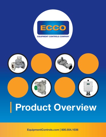
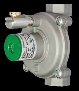
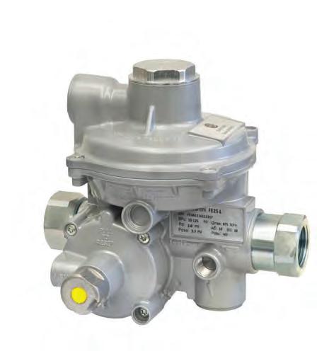
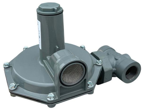
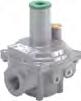
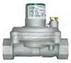
REGULATORS
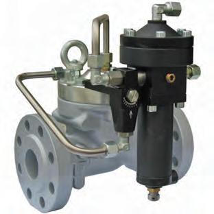
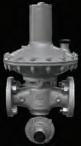
PF400
Line Pressure Regulators
Pietro Fiorentini’s PF400 line of gas regulators are designed to comply with the latest CSA and international standards for regulators suitable for indoor and outdoor installations with no modifications. The PF400 family of regulators are ideal for a wide range of residential through large industrial applications. The materials and soft parts used in the construction of the PF400 regulators make them suitable for use with natural gas, LPG, Propane air and other non-corrosive gases. All PF400 can achieve high outlet pressure accuracy regardless of Inlet pressure variation. The external vent limiter reduces piping costs and the need for costly vent piping for indoor installations and complies with CSA guidelines.*
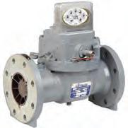
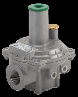
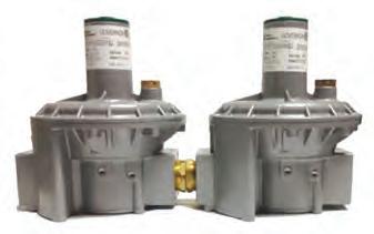
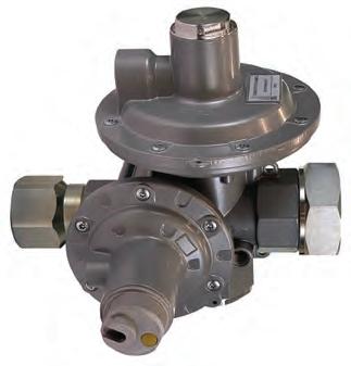
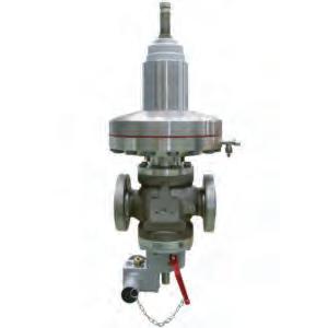
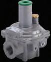
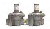
PF GOVERNOR 2 PSIG
Standard Model Regulators
Pietro Fiorentini’s GOVERNOR line of gas regulators are designed to comply with the latest CSA and international standards for regulators suitable for indoor and outdoor installations with no modifications. All GOVERNOR regulators are equipped with balanced valve design for improved high outlet pressure accuracy regardless of Inlet pressure variation. The double diaphragm with integral vent limiter provides added security. The external vent limiter reduces piping costs and the need for costly vent piping for indoor installations and complies with CSA guidelines.* The number of high capacities and regulator options sometimes eliminates the need for separate units and significantly reduces installation costs.
FEATURES
• ANSI Z21.80A-2019 / CSA 6.22A-2019 Class I for outlet pressures up to 14” W.C. Certified
• ANSI Z21.18B-2019 / CSA 6.3B-2019 for inlet pressure up to 5 PSIG certified
• Integral Vent Limiter
• External Vent Limiter – no vent line required**
• Positive 100% bubble tight lockup
• Inlet and Outlet test ports
• 500:1 Turndown
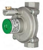
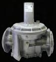
GOVERNOR 10 PSIG
Over Pressure Device
CSA design certified Z21.80/ CSA 6.22 Class I Line Gas Pressure Regulator with Over Pressure Protection (OPD) for 10 PSIG inlet pressure, outlet pressure range of 2” W.C. to 1/2 PSIG. The GOVERNOR allows for vent limited**, multi-position installation and positive dead-end lockup for 1/2” through 2” . The GOVERNOR Gas Pressure Regulator also features double diaphragm, integral vent limiter with balanced valve design to provide increased capacity and accuracy. The GOVERNOR is suitable for indoor and outdoor installation.
FEATURES
• Worker and Monitor for added safety
• ANSI Z21.80A-2019/ CSA 6.22A-2019 Class I up to 14" W.C. and Class II for outlet pressures up to 1 PSIG and inlet pressures up to 10 PSIG Certified
• ANSI Z21.18B-2019 / CSA 6.3B-2019 for inlet pressure up to 5 PSIG certified
• Integral Vent Limiter
• External Vent Limiter – no vent line required**
• Positive 100% bubble tight lockup
• Inlet and outlet test ports
• 500:1 Turndown
*As Approved by
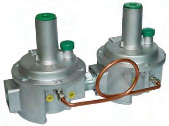
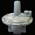
GOVERNOR Dual Cut 10 PSIG
Line Gas Pressure Regulator with Over Pressure Protection (OPD)
CSA design certified Z21.80/ CSA 6.22 Class I Line Gas Pressure Regulator with Over Pressure Protection (OPD) for 5 PSIG inlet pressure, outlet pressure range of 2” W.C. to 1 PSIG. The GOVERNOR allows for vent limited**, multi-position installation and positive dead-end lockup for 1/2” through 2”. The GOVERNOR Gas Pressure Regulator also features double diaphragm, integral vent limiter with balanced valve design to provide increased capacity and accuracy. The GOVERNOR is suitable for indoor and outdoor installation.**
FEATURES
• Two stage regulation for over pressure protection
• ANSI Z21.80A-2019/ CSA 6.22A-2019 Class I up to 14" W.C. and Class II for outlet pressures up to 1 PSIG and inlet pressures up to 10 PSIG Certified
• ANSI Z21.18B-2019 / CSA 6.3B-2019 for inlet pressure up to 10 PSIG certified
• Integral Vent Limiter
• External Vent Limiter – no vent line required**
• Positive 100% bubble tight lockup
• Inlet and outlet test ports
• 500:1 Turndown
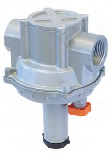
PF Zero/Ratio
Low Pressure Gas Pressure Regulators
Double diaphragm safety governor, Zero Governor is designed to maintain a constant gas/air ratio even when the flow varies and to ensure that downstream of the regulator the pressure is zero. The entire F3Z regulator family is ideal for all burner installations, mixing nozzles and proportional premixers. It can be used with previously filtered non-corrosive gases and is widely used in the construction of low pressure natural gas distribution networks for industrial, commercial and residential users.
FEATURES
• Design pressure: 1 bar
• Design temperature: from -10° C to +60° C
• Max. inlet pressure: 0.35 bar
• Output pressure range: from -5 mbar to +5 mbar
• Minimum differential pressure: 20 mbar
• Air connections: 1/4” and 1/2” for DN>1” ISO 228 1/2” for DN>1”
The Cirval is available in two sizes: the Cirval 200 8” head and the Cirval 300 12” head. Pietro Fiorentini’s Cirval design is controlled by a diaphragm setting spring, which controls a balanced valve cartridge. Typical applications for the Cirval are medium and low pressure natural gas distribution systems, as well as commercial and industrial applications.
FEATURES
• Design pressure*: up go 125 PSIG
• Ambient temperature*: from -20°F to +150°F
• Inlet gas temperature range*: from -4°F to +140°F
• Inlet pressure range bpu (MAOP): from 2 to 75 PSIG
• Range of downstream pressure Wd: from 7” W.C. to 10 PSIG
• Available accessories: LA slam shut, IMD (Independent Monitoring Device), IFM (Integral Full Monitor), built-in strainer
REGULATORS
PF Dival 500
Direct-Acting
Gas Pressure Regulators
The DIVAL 500 series of spring loaded, diaphragm controlled balanced plug gas regulators are suitable for low, medium and high pressure. Divals and shut-off device series regulators are supplied with internal sensing lines. Both the regulator and the shut-off device are preset for optional connection to an external sensing line by the customer. They are widely used in both civil and industrial installations using Natural Gas, LPG and other non-corrosive gases.
FEATURES
• Accuracy class: Up to 10
• Available size DN: 1” – 1” 1/2
• Closing pressure class SG: Up to 10
• Design pressure: BP: 10 bar MP / TR: 20 bar
• Design temperature: -20°C to 60°C
• Outlet pressure range of Wd: BP 13- 100 mbar MP 100 – 300 mbar TR 300 – 2500 mbar
• Range of inlet pressure bpu: BP: 0.5÷10 bar MP / TR: 0.5÷20 bar
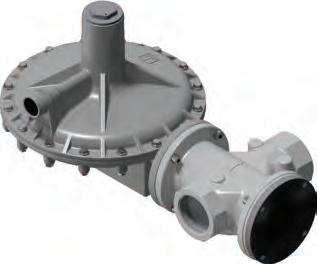
PF Dival 600
Direct-Acting
Gas Pressure Regulators
Dival 600 series pressure regulators are direct acting devices for low and medium pressure applications controlled by a diaphragm and counter spring. These regulators are suitable for use with previously filtered, non corrosive gases.The modular design of the Dival 600 series allows for the addition of a slam shut or an in-line monitor device in the same body without changing the face-to-face dimensions. The truly “top entry design” allows easy periodic maintenance without removing body from the line. The features of Dival 600 series regulators make it a product suitable for any application.
FEATURES
• Design pressure 232 PSIG for all the components
• Accuracy (AC): 1% of the pressure set-point for pressure increase; 5% for pressure decreasing
• Internal bypass
• Intervention for over pressure and/or under pressure
• Manual push-button control
• Possibility of pneumatic or electromagnetic remote control
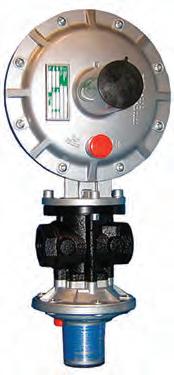
PF Goval
Line Pressure Regulator
Pietro Fiorentini’s GOVAL line of gas regulators are designed to comply with the latest CSA and international standards for regulators suitable for indoor and outdoor installations with no modifications. The GOVAL family of regulators are ideal for a wide range of residential through large industrial applications. The materials and soft parts used in the construction of the GOVAL regulators make them suitable for use with natural gas, LPG, Propane air and other non-corrosive gases. All GOVAL regulators are equipped with balanced valve design for improved high outlet pressure accuracy regardless of Inlet pressure variation.
FEATURES
• Max. inlet 15 PSIG for Non-CSA applications
• CSA 6.22A-2005 ANSI Z21.80A 2019 Class I for outlet pressures up to 2 PSIG
• Integral Vent Limiter
• External Vent Limiter – no vent line required**
• Positive 100% bubble tight lock up
• Inlet and Outlet test ports
• 500:1 Turndown
PF Norval
Direct-Acting Gas Pressure Regulators
The NORVAL is a downstream pressure regulator, self actuated, spring loaded for medium and low pressure applications. It is suitable for gaseous, non-corrosive, previously filtered fluids. It’s balanced valve design gives quick response to varying operating conditions, which make it particularly suitable for use when serving ON-OFF burners and in any industrial process where you have a quick change of the flow rate.
FEATURES
• Maximum inlet pressure up to:
• 284 PSIG for regulators from 1” to 3”
• 116 PSIG for regulators from 4” to 8”
• 275 PSIG for steel body and 246 PSIG for ductile Iron
• Range of downstream pressure:
• from 4” W.C. to 63.81 PSIG for regulators from 1” to 4”
• from 4.8” W.C. to 26.10 PSIG for regulators 6” and 8”
• Minimum ambient temperature: execution up to -40°F (to specify in the request)
• Maximum ambient temperature: +140°F
• Flowing gas temperature: up to -4°F to +140°F
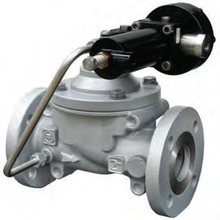
PF Reval 182
Pilot-Operated Gas Pressure Regulators
The Reval 182 is a pilot-controlled pressure regulator for medium and low pressure. The Reval 182 is a ‘fail close’ regulator. It closes if:
• The main diaphragm fails;
• The pilot diaphragm/s fail; or
• There is no feed to the pilot loop.
FEATURES
• Accuracy class
• Available size DN
• Closing pressure class SG
• Design pressure
• Design temperature
• Flanging
• Maximum working differential pressure
• Minimum working differential pressure
• Outlet pressure range of Wd
• Range of inlet pressure bpu
PF Dilock Safety Device
Dilock is a safety device (SAV) which quickly shuts off the gas flow when the pressure it is monitoring reaches a pre-set limit due to any abnomality in the system, or when required by the operator to operate from a remote point.
FEATURES
• Max. inlet pressure Pe max: 274 PSIG
• Gas operating temperature: – 4 °F to +140 °F
• Ambient temperature: – 40 °F to +140 °F
• Range of outlet pressure Wh: .43 to 79.77 PSIG
• Accuracy: AG ± 5% on the value of the pressure setting
• Intervention on pressure increase and/or decrease
• Option for pneumatic or electromagnetic remote control
• Manual re-setting with internal by-pass activated by the maneuvering lever
• Possibility of application of devices for intervention remote signal (contact switches or proximity switches)
REGULATORS
PF Mod. FE
Residential Gas Pressure Regulators
FE is a double-stage self-operated pressure regulator for civil and industrial applications and it is suitable for use with gaseous fluids such as natural gas, LPG and non-corrosive gases. These regulators are designed to be installed directly on utility meters or on riser mains for civil uses. They can be installed in any position and in environments or spaces protected against weather. The discharge of the internal relief valve can be conveyed outside in case of installation in closed rooms or underground installations.
FEATURES
• Inlet pressure range bpu: 4.3 – 125 PSIG
• Max allowable pressure: PS: 125 PSIG
• Outlet pressure range BP: 5 – 72.3” W.C.
• Accuracy class AC: up to 5%
• Lock up pressure class: up to 10%
• Temperature: Gas Temperature -4°F +140°F and Ambient Temperature -40 to +140 °F
PF Mod. FEX
Commercial Service Regulator
The FEX series of two-stage self-driven spring loaded regulators are widely used in both commercial and industrial installations using natural gas, LPG and other non-corrosive gases. They are designed for direct installation to a gas meter and for use in general pipeline work. They can be mounted in any position provided the vent is protected from weather. When the installation is in an enclosed area, the internal relief vent can be piped outside. A balanced, two-stage regulator results in accurate regulation and high operational reliability.
FEATURES
• Inlet pressure range: bpu: 4.35 -125 PSIG
• Max allowable pressure: PS: 125 PSIG
• Accuracy class: AC 5/10%
• Lock up pressure class: SG 30% Max
• Temperature class: 2: -68°F+140°F
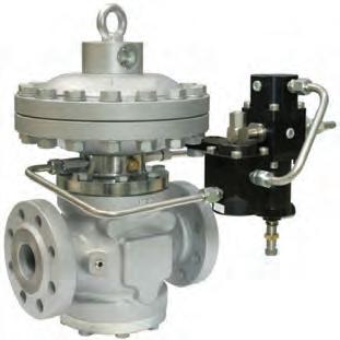
PF Aperval
Pilot-Operated Gas Pressure Regulators
Aperval is a pilot-controlled pressure regulator for medium and low pressure applications. Aperval is normally a fail open regulator and will open specifically under the following conditions:
• Breakage of main diaphragm
• Lack of sensing line connection
This regulator is suitable for use with previously-filtered, non-corrosive gases.
FEATURES
• Accuracy class AC: Up to 2.5% guage
• Design inlet pressure: 275 PSIG
• Range of inlet pressure: 7.25 to 275 PSIG
• Range of downstream pressure: 2” W.C. to 137.5 PSIG depending on installed pilot
• Minimum working differential pressure: 7.5 PSIG
• Minimum ambient temperature: Execution up -40°F
• Maximum ambient temperature: 140°F
• Flowing gas temperature: -4°F to 140°F
• Accuracy class AC: Up to 2.5% gauge
• Lock-up pressure class SG: Up to 5% gauge
PF Reflux
Pilot-Operated Gas Pressure Regulators
It is particularly suitable for high-pressure transmission systems and for medium pressure natural gas distribution networks, and it can be used with previously filtered non-corrosive gases.
According to the European Standard EN 334, it is classified as Fail Close (pilot series 200/A) or Fail Open (pilot series 210/A) according to the installed pilot (except for the PM819 monitor).
• Design temperature: from -20 °C to +60 °C (higher or lower temperatures on demand)
• Connections: class 150, 300, 600 RF or RTJ according to ASME B16.5 and PN 16 according to ISO 7005
• Minimum working differential pressure: 0.5 bar
• Range of downstream pressure Wd: from 0.3 to 74 bar
• Inlet pressure range bpu: from 0.8 to 100 bar
PF Aperflux
Pilot-Operated Gas Pressure Regulators
Particularly suitable for high-pressure transmission systems and for medium pressure natural gas distribution networks, it can be used with previously filtered non-corrosive gases.
FEATURES
• Accuracy class AC: up to 2.5
• Nominal sizes DN: 2”, 3”, 4”
• Lock-up pressure class SG: up to 10
• Design pressure: up to 85 bar
• Design temperature: from -20 °C to +60 °C (higher or lower temperatures on demand)
• Connections: class 300 and 600 RF or RTJ according to ASME B16.5
• Minimum differential pressure: 1 bar, recommended > 2 bar
• Range of downstream pressure Wd: from 0.8 to 74 bar
• Inlet pressure range bpu: from 1.8 to 85 bar
PF Norflux
Direct-Operated Gas Pressure Regulators
Norflux is a direct-operated regulator controlled by a diaphragm and setting spring which controls the valve. It is mainly used for highpressure transmission systems and for medium pressure natural gas distribution networks with previously filtered non-corrosive gases.
FEATURES
• Design pressure: up to 1450 psig | 10.0 MPa
• Inlet gas temperature: from -4 °F to +140 °F | from -20 °C to +60 °C
• Range of downstream pressure: from 10 to 65 psig | from 0.07 to 0.45 MPa
• Accuracy class: up to 10 (depending on working conditions)
• Lock-up pressure class: up to 10 (depending on working conditions)
• Nominal size: DN 50 | 2”
• Connections: Class 300/600 RF / RTJ according to ASME B 16.5
REGULATORS
USG 496
Domestic Gas Regulator
Like others in our family of service regulators, our 496 Domestic service regulators offer rugged construction for a lifetime of reliable service. They feature precise pressure control and outstanding performance and dependability.
496 Domestic service regulators can be used for residential meter sets as well as small commercial and industrial applications, including burners, furnaces, ovens, heaters, gas engines and others. They offer a variety of body and orifice sizes and load springs settings. The 4” roll-out diaphragm offers exceptional performance, and it provides capacities that normally require 6” diaphragm regulators. This domestic gas regulator is available with an internal relief valve as a standard feature.
Designed for Broad Output Pressure Ranges
BENEFITS
• Installs in numerous mounting positions
• Delivers precise pressure control
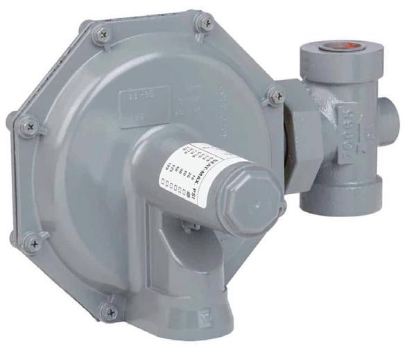
USG 143-80 Domestic Service Regulators
FEATURES
• Five different outlet pressure ranges
• Angled or straight configuration
Like others in our family of service regulators, our Domestic 143-80 models are built to perform. They feature precise pressure control and outstanding performance and dependability. These residential gas regulators are also available with a low-pressure cut-off. The Domestic 143-80 design offers smart features, including an internal relief valve as well as union nut connection, which does not require bolts or screws to connect the body to the diaphragm assembly. This enables the regulators to be set in virtually any position for excellent field versatility.
BENEFITS
• Installs in numerous mounting positions
• Delivers precise pressure control
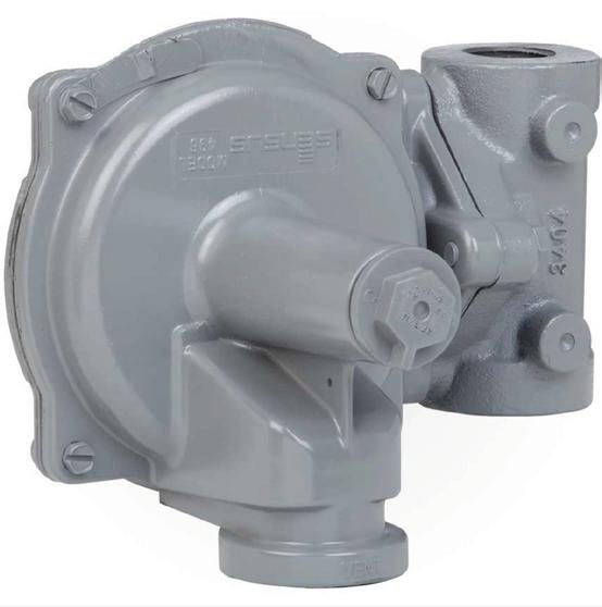
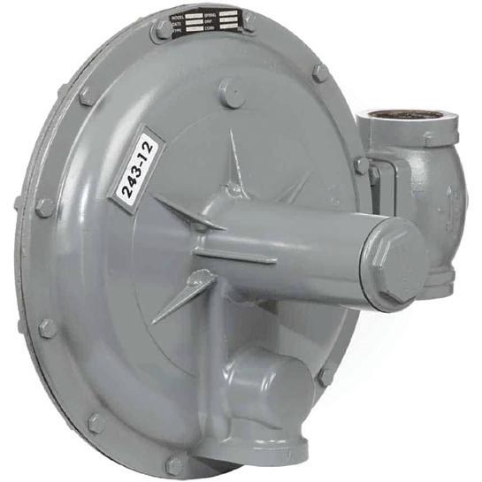
USG 243
Commercial
Natural Gas Regulators
FEATURES
• Low-pressure cut-off available
• Internal relief valve available
• Seven outlet pressure ranges
243 commercial regulators can be found in factories, foundries, district regulator stations, commercial laundries and laundromats. These versatile natural gas regulators are ideal for commercial use such as apartments, restaurants, schools and hospitals. Their design works well for all types of gas-fueled equipment, too. This includes: boilers, burners, furnaces, ovens, heaters, kilns and engines.
BENEFITS
• Installs and adjusts easily
• Allows for pressure factor measurement, pressure compensated metering and fixed factor billing.
FEATURES
• Special material available for certain corrosive gases
• Available with low-pressure cut-off
• Available with internal relief valve
• Interchangeable bodies and diaphragm-case assemblies
• High-pressure model available
• Pilot-operated model available
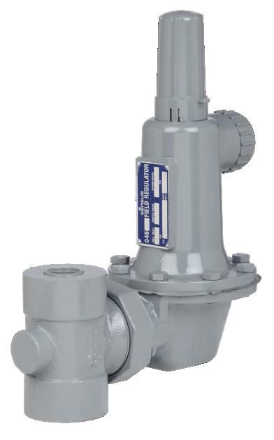
USG 046
Industrial Combustion Regulators
Our 046 field and high-pressure gas regulators combine simple design and rugged construction for exceptional performance and operational safety. They feature dependable, flexible and economical answers for pounds-to-pounds pressure regulation applications. The 046 family of high-pressure gas regulators are easy to install, adjust, inspect and service in all piping arrangements. Typical applications include farm taps, field regulator applications, high-pressure industrial air or gases and gas blanketing systems.
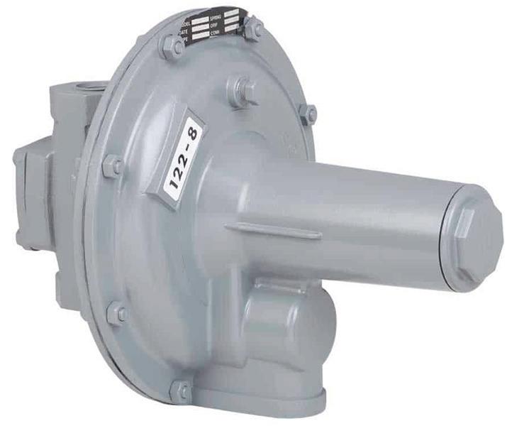
USG 121/122
Industrial Combustion Regulators
Achieve greater capacity, higher inlet pressure, more accurate performance and a faster response for higher volume commercial/industrial applications with our industrial combustion regulators. These regulators provide an unbeatable combination of capacity, performance and economy. Both the Model 121 and Model 122 are highly functional regulators that feature die-cast diaphragm cases and cast iron bodies. This makes them strong and corrosion resistant. Both models incorporate soft-seat valve material, plus a precision-machined “knife edge” orifice for a positive, tight shutoff.
BENEFITS
• Allows above-ground or vault installation
• Provides for pilot-operated, pressure-loaded and V-port options
• Serves high-capacity installations
• Allows high inlet pressures
Belgas Type P140
Pressure Regulator-Non
Relieving
The Type P140 pressure regulator is ideal for natural gas, air, propane and general purpose gas pressure regulation. Uses include commercial, residential and light industrial for burners and unit heaters. Available with or without internal relief. Applicable to a wide range of gaseous fluids, including air, natural gas and propane. Can be used as a LP regulator.
FEATURES
• Versatile
• Control accuracy
• Compact design
Belgas Type P143
Natural Gas Service Regulator
The Type P143 gas pressure regulator from BelGAS is ideal for natural gas, air, propane and general purpose gas pressure regulation. Uses include commercial, residential and light industrial for burners and unit heaters. The Type P143 has an internal relief device and is available in the low pressure cut off – LPCO – version. The regulator is applicable to a wide range of gaseous fluids, including air, natural gas and propane. Can be used as a LP regulator.
FEATURES
• Versatile
• Control accuracy
• Compact design
• Low pressure cut-off
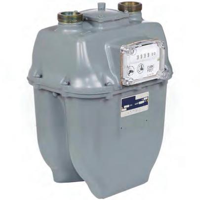
METERS
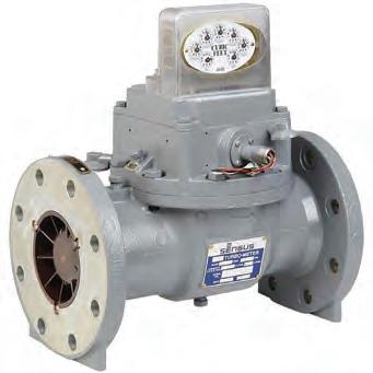
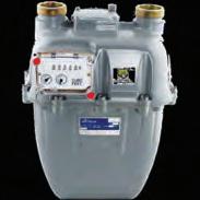
Sensus R-275
Residential Gas Meters
The R-275 and R-315 are Class 250 residential diaphragm gas meters that combine the latest design concepts and modern engineering materials. Lighter weight and easy to handle, they are more durable, require less maintenance and offer greater life expectancy than previous meters in this class.
The temperature compensation element has increased strength to minimize deflection from valve drag. A simplified crank bracket provides accurate positioning of the crank support, and its low-friction polymer material eliminates the need for lubrication. Close tolerances and molded phenolic construction of the valve seat provide smoother operation and minimize wear. The R-275 and R-315 meters also accommodate external valve guides, which are easily installed in these meters.
Our revolutionary, patented accuWAVE diaphragm is now standard on the R-275 and R-315 meters. This design has a longer life expectancy, improved long-term performance—even in extreme conditions—exceptional proof stability and a lower overall lifetime cost.
BENEFITS
• Lowers total cost of ownership
• Reduces repair time and cost
• Increases efficiency
• Extends life span
FEATURES
• accuWAVE diaphragm
• Operating temperature range: -30° F to 150° F
• Larger volume applications
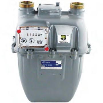
Sensus 415
Diaphragm Meter
The 415 is a Class 400 residential, commercial and industrial diaphragm meter that combines the latest design concepts and modern engineering materials. Lighter weight and easy to handle, the 415 is more durable, requires less maintenance and offers greater life expectancy than previous meters in this class.
The temperature compensation element has increased strength to minimize deflection from valve drag. A simplified crank bracket provides accurate positioning of the crank support, and its low-friction polymer material eliminates the need for lubrication. Close tolerances and molded phenolic construction of the valve seat provide smoother operation and minimize wear. It accommodates external valve guides, which are easily installed in this meter. Our revolutionary, patented accuWAVE diaphragm meter is now standard on the 415 meter. This design has a longer life expectancy, improved long-term performance—even in extreme conditions—exceptional proof stability and a lower overall lifetime cost.
BENEFITS
• Lowers total cost of ownership
• Reduces repair time and cost
• Increases efficiency
• Extends life span
FEATURES
• accuWAVE diaphragm
• Operating temperature range: -30° F to 150° F
• Larger volume
SPECIFICATIONS
Capacity (ft³/h):
• Natural gas: 415
• Butane: 225
• Propane: 260
• Air: 320
Sensus Auto-Adjust® II Turbo Meters
The Most Advanced Gas Turbine Meter Technology Ever Produced
Deliver unparalleled high volume gas measurement with the Auto-Adjust II turbo meter (AAT). It features dual sensing rotors and patented algorithms that work in partnership to detect and adjust for changes in gas flow conditions, such as jetting, pulsation and swirl. They can also adjust for drag caused by component wear or contamination. In fact, Auto-Adjust II meter accuracy is +/- 1.0% over the entire operating range of the gas turbine meter.
Using the same top-entry design of our Mark II turbo meters, the measuring module of the AAT can be changed, recalibrated or upgraded without removing the meter body from the line. This helps prevent costly downtime and lost revenue. The AAT meter has unique self-checking features. So you can provide constant accuracy monitoring and in-line field diagnostics—a good way to save significant maintenance dollars.
BENEFITS
• Alerts users to unstable upstream conditions and unacceptable installations
• Allows for remote monitoring of measurement system accuracy
• Allows for remote totalization of adjusted and corrected volumes
• Reduces the number of maintenance and testing site visits
FEATURES
• Dual turbine technology
• Removable measuring module
• Accuracy savings
• Maintenance savings
• Auto-adjusting design
• Self-checking and self-adjusting algorithm
• Easy upgrades and customization
Sonix IQ
Unprecedented performance from a sleek, ultrasonic standout
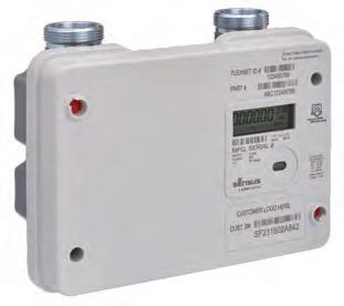
Sonix IQ provides the pinpoint accuracy of ultrasonic measurement for residential gas metering. Designed to meet rigorous standards required for outdoor installations in North America, this solid state meter has no moving parts to replace or wear out over time. It boasts dual-class metrology; the same size meter can cover either 250 CFH or 425 CFH needs. And with an available FlexNet® radio integrated inside the meter housing – the Sonix IQ packs in value within a compact size. No other gas turbine meter technology offers the self-checking accuracy, convenient maintenance and continuous measurement certainty as the Auto-Adjust II.
BENEFITS
• Compact footprint to fit anywhere
• Two-way communications when used with a Sensus FlexNet® communication network
• Supports third party radios
• Continuous health checks through safety alerts and alarms
• Streamlined asset management planning and reduced costs due to solid-state construction, integrated communication module and extended 20-year battery life
FEATURES SEE ALSO
• Dual-class metrology: 250 CFH or 425 CFH
• 90-day hourly data logs
• Built-in theft and tamper detection
• Available pulse output
• Optional FlexNet capability
• Sonix 600/880 Ultrasonic Meter
• Sonix 2000/3000
METERS
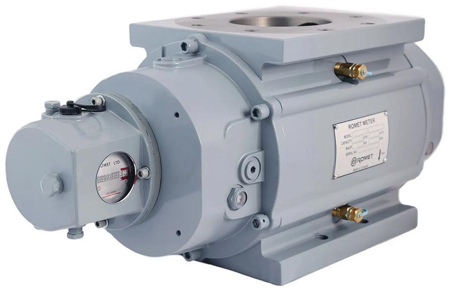
ROMET ® RMT
Rotary Gas Meters
The RMT meter is ROMET’s most advanced meter body. The extruded aluminum body along with our proprietary impeller profile provides improved rangeability while maintaining the highest levels of accuracy and precision through our patented pinned timing gear design. An integral mechanical backup counter comes standard on the entire RMT size range providing our customers with the peace of mind that accurate and reliable measurement will be maintained throughout the life of the meter.
RUGGED
All meters are pressure tested up to 4x MAOP to ensure only the toughest meters leave our facility.
RESPONSIVE
Each meter is individually factory tested and certified for measurement accuracy meeting or exceeding ANSI B109.3 rotary gas meter requirements.
RELIABLE
RMT meters come standard with an integral mechanical backup counter to give our customers confidence that reliable measurement will always be achieved.
In a world where operational efficiency and energy cost control are paramount, Romet’s BrightLink™ Energy Management System delivers a cutting-edge, turnkey solution to help commercial and industrial facilities take control of their energy usage and performance.
KEY BENEFITS AND CAPABILITIES
BrightLink™ seamlessly integrates gas measurement, real-time monitoring, data acquisition, and intelligent analytics into a unified platform designed for today’s energy-intensive environments. Whether you're managing a single facility or a multi-site operation, BrightLink™ empowers your team with actionable insights and tools to:
• Monitor Natural Gas Flow & Pressure in real time with precision and reliability.
• Track Energy Consumption Trends across multiple sites, departments, or equipment types.
• Automate Data Logging and Compliance Reporting to meet regulatory requirements with ease.
• Identify Cost-Saving Opportunities through smart analytics and custom alerts.
• Enhance Operational Efficiency by integrating with SCADA, DCS, or building automation systems.
Built on Romet’s proven legacy of measurement and control, BrightLink™ supports a full suite of hardware and software tools tailored to your facility’s needs, including remote telemetry units (RTUs), cloud dashboards, and API integration for enterprise-level energy management.
Whether you're looking to reduce energy waste, optimize load management, or enhance sustainability metrics, Romet BrightLink™ offers the clarity, control, and confidence to power smarter decisions.
YOUR FACILITY. YOUR DATA. YOUR ADVANTAGE.
Choose Romet BrightLink™ and unlock the full potential of your energy infrastructure.
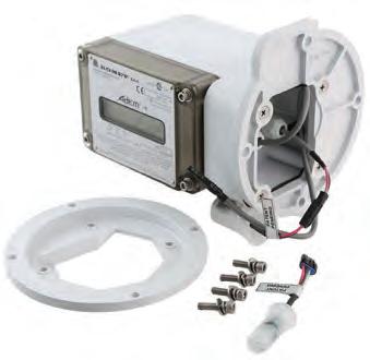
AdEM®-T
Rotary Meter
The AdEM is compact, rugged, service-free, tamper-proof and weather resistant with a high level of accuracy and customization. With a nominal battery life of 15-20 years, the AdEM makes an ideal upgrade to any system requiring instrumentation.
An electronic counter module with the capability for live Temperature compensation. The AdEM-T is best suited for applications where live temperature compensation is required. For applications where pressure can be predetermined and compensation is required, a fixed pressure factor can be applied. The AdEM-T is a direct mount module for seamless integration with ROMET® and other popular rotary meters. Some features of the AdEM-T include a full audit trail, four available output pulses, serial communication and a 20 year nominal battery life.
One Size Fits All- upgrade your rotary meters with the latest electronics in a matter of a click.
ROMET has developed a single adapter plate that will allow our AdEM-T to be installed on ROMET RM 600-56000 rotary meters and RMT 600-23000 rotary meters. We also offer a single adapter plate for Dresser B3 meters ranging from 8C to 56000 and LMMA meters ranging from 1500-16000. The AdEM-T comes standard with ROMET’s patented AdEM Click technology allowing for seamless installation between ROMET and Dresser rotary meters.
With the AdEM Click you can carry one electronic corrector to fit all sizes and brands of rotary meters in your system.
BENEFITS
• Simple
• Reduced inventory
• Reduced truck rolls
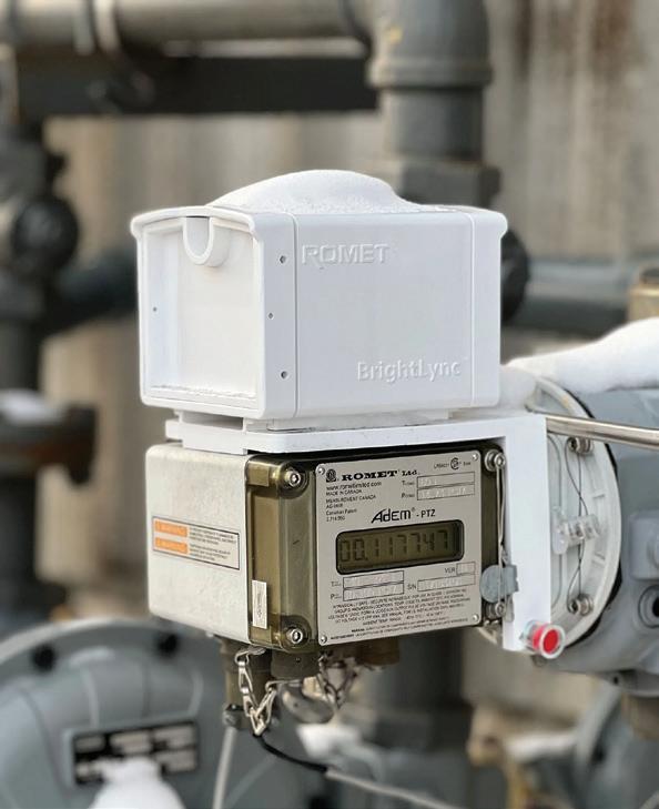
AdEM®-PTZ
Advanced Electronic Module (Pressure, Temperature and Supercompressibility Compensation)
An electronic counter module with the capability for live compensation for Pressure, Temperature and Supercompressibility (Z). The AdEM-PTZ is a direct mount module for seamless integration with ROMET ® and other popular rotary meters. Some features of the AdEM-PTZ include a full audit trail, four available output pulses, serial communication and a 15 year nominal battery life. This state-of-the-art corrector is also available as a remote mount variation- AdEM-PTZ-r.
The AdEM-PTZ is an electronic counter module with the capability for live compensation for Pressure, Temperature and Supercompressibility (Z). The AdEM-PTZ is a direct mount module for seamless integration with ROMET and other popular rotary meters. Some features of the AdEM-PTZ include a full audit trail, four available output pulses, serial communication and a 15 year nominal battery life. This state-of-the-art corrector is also available as a remote mount variation- AdEM-PTZ-r.
One Size Fits All- upgrade your rotary meters with the latest electronics in a matter of a click.
ROMET has developed a single adapter plate that will allow our AdEM-PTZ to be installed on ROMET RM 600-56000 rotary meters and RMT 600-23000 rotary meters. We also offer a single adapter plate for Dresser B3 meters ranging from 8C to 56000 and LMMA meters ranging from 1500-16000. The AdEM-PTZ comes standard with ROMET’s patented AdEM Click technology allowing for seamless installation between Romet and Dresser rotary meters.
With the AdEM Click you can carry one electronic corrector to fit all sizes and brands of rotary meters in your system.
VALVES + ACCESSORIES
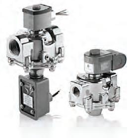
ASCO Solenoid Valves
ASCO offers solenoid valves for virtually any application. Models include general purpose, explosion-proof, intrinsically safe, combustion, and air-operated. They are available in brass, stainless steel, plastic, and aluminum bodies. Enclosures are available to operate from -40°c to 200°c in normal and hostile or explosive environments.
General purpose valves are available to control air, water, light oil, and gases. Pipe sizes of 2 way solenoid valves are available from 1/8" to 3". Pipe sizes of 3-way solenoid valves range from 1/8" to 1". The pipe size range of 4-way valves is 1/4" to 1".
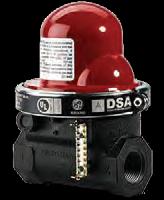
Pacific Seismic Shut-Off Valves
Pacific Seismic/California Valves are earthquake sensitive gas shut-off valves. They are intended to close in the event of an earthquake to prevent gas flow into a structure where earthquake damage may have occurred. The valve reduces the potential for fire or explosion due to the release of natural gas into a structure where gas lines, gas fixtures or gas appliances.
PSP valves do not use any source of internal or external electrical power. They are designed to remain closed until manually reset. The valves are intended to be mounted in the gas line upstream or downstream of the gas-line pressure regulator and gas meter outside the structure. These valves do not replace the manual upstream shut-off valves provided in the gas service line.
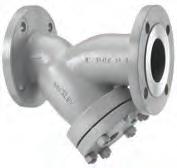
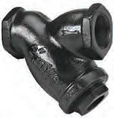
Keckley Pipeline Strainers
Keckley Y-strainers are furnished standard with drain connections and pipe plugs. Most commonly, Y-strainers are fitted in the field with nipples and drain valves to permit the strainer screen to be cleaned while the system is still in process. By opening the drain valve while the system is under pressure, the debris trapped in the screen is "blown" through this connection helping to reduce system shut-downs for maintenance and cleaning.
The Keckley Company offers many industrial & commercial pipeline strainer options to include epoxy coatings, galvanizing, oxygen cleaning, special tapings, specialty flange connections & NDE testing. These specialty strainer options are available for Y-strainers, simplex basket strainers, duplex basket strainers, and our fabricated product line.
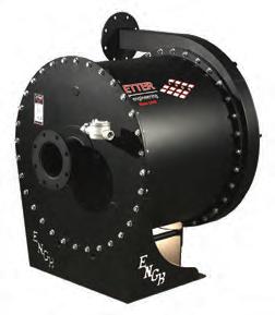
ETTER Gas Boosters
GAS On Demand – The Plug and Play Option
ETTER Engineering’s skid-mounted packaged booster systems arrive at your job site prepiped, wired, tested, and ready to work. On-site installation is quick and easy – simply mount the skid in place, connect electrical power to the control panel (and interlock to load equipment as necessary), bolt the system’s supply and discharge piping to the field piping, then flip the switch!
This method of installing a gas booster system is more cost effective when compared to purchasing loose components for your contractor to install in the field. As a client commented, “ETTER’s packaged boosters are as close to Plug & Play as it comes for a booster project! Using their complete system saved us both time and money.”
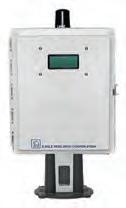
XARTU/1™
Volume Corrector
The XARTU/1-LDVI™ Volume Corrector is the core product in the volume corrector line. This unit runs on the proven XARTU/1™ SBC61 circuit board, heart of all products in the Eagle XA/1 series. The VC-LDVI includes an internal pressure transducer, an internal RTD (resistance temperature detector), external display and 2400 bps modem in the standard product offering. An optional Low Drag Vertical Index (LDVI™) provides the user with a low cost mechanical backup to the electronic device.eds
BENEFITS
• Low Drag Vertical Index (LDVI)
• Single and bi-directional versions available
• AGA 7, AGA 8 (Detail & Gross Method I & II), and NX-19
• Wide choice of pressure ranges (absolute or gauge)
• 100 ohm Platinum RTD (resistance temperature detector)
• Digital outputs for corrected/uncorrected volumes
• Configurable for forward, reverse and net volumes
• Power requirement dependent on communications method and frequency
• Multi-Run configurations available using a transducer interface or XDI
• Warranty: four years on all EAGLE RESEARCH manufactured components
GAS REGULATOR INFORMATION REQUIRED
CAPACITY (in MBH, CFH,BTU)
INDOORS OR OUTDOORS
a. IF INDOORS, DO THEY WANT VENT LIMITED?
7. TYPE OF EQUIPMENT
TYPE OF GAS - Either Natural Gas (NG) or Liquid Propane (LP).
INLET PRESSURE - This is the pressure coming from the gas meter / gas company, or LP tank, not what the equipment requires.
OUTLET PRESSURE - This is the operating pressure of the appliance. Most contractors only give you the max operating pressure of 14", but that is simply the maximum pressure the equipment will continue to operate. All equipment has a MIN and MAX stamped on the plate or shown in the specs. You need to find out the actual operating pressure required by the appliance. For natural gas, it is usually 8" W.C. For LP, it is usually 11" W.C. If you don't know what it is, you will get a quote for a regulator with a 7-11" W.C. or 6-14" W.C. range. These will work on 99% of all applications anyway.
REGULATOR SIZE IS RECOMMENDED - To match the downstream pipe size and/or the gas connection size on the appliance.
CAPACITY - This will be stated as BTU, MBH, CFH or SCFH. They are all basically the same and I can quote regulators on however it is listed. BTU is listed as the complete number, whereas MBH, CFH and SCFH have the last three zeros dropped. For example, 250,000 BTU is the same as 250 MBH or CFH.
INDOORS OR OUTDOORS - This will determine whether a vent limiter (indoors only) or a vent protector/cap (outdoors only) is needed.
a. VENTED OR VENT LIMITED – If mounted indoors do they want to go vent limited.
TYPE OF EQUIPMENT - If the type of equipment is not specified, you will be quoted a regulator that will work on all types of equipment, including a generator and high efficiency boiler, which could result in a much more expensive regulator than needed.
GAS REGULATOR APPLICATION WORKSHEET
from the gas source (meter, utility company, or LP tank), not the pressure the appliance requires.
Outlet Pressure – This is the pressure required by the appliance to operate correctly. Many contractors only provide the maximum operating pressure (typically 14" w.c.), but that just means the highest pressure the equipment can handle. Every appliance has both a minimum and maximum operating pressure listed on its data plate or in its specifications.
For Natural Gas, the typical requirement is 8" w.c. For LP, it’s usually 11" w.c.
If the exact requirement isn't known, you'll likely receive a quote for a regulator with a 7–11" w.c. or 6–14" w.c. range—suitable for the vast majority of applications.
Regulator Size – Should match the downstream piping or the appliance’s gas connection size.
Capacity – Indicated as BTU, MBH, CFH, or SCFH. These all refer to the same measurement, just expressed differently:
BTU is the full number (e.g., 250,000 BTU)
MBH, CFH, and SCFH drop the last three digits (e.g., 250
MBH = 250,000 BTU)
We can quote based on any of these formats.
Indoor or Outdoor Installation – This determines the venting accessory required:
Vent limiter for indoor use
Vent protector or cap for outdoor use
Vented or Vent-Limited – For indoor installations, determine whether a vent-limited regulator is preferred.
Type of Equipment – If not specified, the quote will default to a universal regulator suitable for various equipment types (e.g., generators, high-efficiency boilers). This can lead to a more expensive regulator than necessary.
•
TOPICS INCLUDE:
• Purpose of gas regulators
• Basics of gas pressures and flow
• Mechanical technologies at play
• Understanding key gas terms
• Introduction to standards and codes
• Application-based sizing and selection
• Installation best practices
• Venting and piping
• Troubleshooting
This presentation provides an in-depth look at gas regulators and over pressure protection.
TOPICS INCLUDE:
Over pressure protection for line pressure regulators
Four major ways of providing over pressure protection
Relief valve operation
Automatic shutoff valves
Compliant vs certified
TOPICS INCLUDE:
•
•
Understanding Line Pressure Regulators
• • • Understanding Gas Codes and Applications
Standards, Certifications, Codes
Regulator Venting
Integral Vent Limiting (Vent Limited Regulators)
at regulator installation and troubleshooting.
A 1-hour overview of gas regulator basics, including how a regulator works, where they are used, and proper installation. •
•
This course provides an overview
the
regulator sizing and selection process.
TOPICS INCLUDE: This presentation provides an in-depth
basics
• • Review of gas regulator
Installation best practices
Proper installation of downstream control lines
Examples of installations FAQ troubleshooting scenarios
Gas Regulator sizing online tools TOPICS INCLUDE:
Information required for sizing and selecting gas regulators
The importance of sizing and selection Turndown ratio
Why droop is important
Basic understanding of diaphragm meters
Basic understanding of turbine meters
Basic understanding of ultra sonic meters
Review of pressure and temperature
gas laws pertaining to gas flow correction
ANSI
ANSI STANDARDS PLAYBOOK
WHAT IS ANSI?
ANSI is the American National Standards Institute. Established in 1918, ANSI serves as a vital hub for coordinating voluntary standards and conformity assessment processes in the United States. Their mission is centered on boosting the competitiveness of American businesses on a global scale, while also improving the quality of life within the U.S. This is achieved through the promotion and facilitation of voluntary consensus standards and conformity assessment systems, ensuring their integrity and effectiveness.
ANSI's role is not to create standards itself but to establish a framework for fair standards development and quality conformity assessment systems. By coordinating the process and ensuring transparency and inclusivity, ANSI helps various stakeholders collaborate effectively in developing standards that meet the needs of industries and society.
WHAT IS CSA AND ITS RELATIONSHIP TO ANSI?
CSA Group, formerly known as the Canadian Standards Association, collaborates closely with ANSI to develop and harmonize standards across various domains, promoting safety, efficiency, and international market compatibility. With expertise in 57 areas, CSA Group plays a crucial role in setting standards that align with ANSI's framework, facilitating smoother trade and manufacturing processes between the United States and Canada. This partnership not only reduces trade barriers but also enhances product safety and quality, benefiting industries and consumers on both sides of the border. Together, CSA Group and ANSI contribute to a more streamlined and effective standards ecosystem, fostering innovation and competitiveness in the global marketplace.
ANSI STANDARDS PLAYBOOK
WHAT IS ANSI Z21.18/CSA 6.3?
Understanding the ANSI Z21.18/CSA 6.3 standard is crucial for ensuring the safety and efficiency of gas appliance pressure regulators. This standard meticulously outlines the requirements for regulators, ensuring they are constructed from new materials and are suitable for a variety of gases, including natural and manufactured gases, as well as liquid petroleum gas (LPG).
The classification of inlet pressures allows for precise selection based on the specific needs of an appliance, whether it's for a main burner or a pilot burner, or even domestic gas ranges. Adherence to this standard is just the first step; additional testing tailored to the appliance's design is necessary to guarantee optimal performance and safety.
It's a comprehensive approach that underscores the importance of precision and care in the manufacturing and application of gas appliance pressure regulators. Compliance with such standards ensure that the devices are not only effective, but also contribute to the overall safety of gas-operated appliances.
The historical practice of using appliance regulators as line pressure regulators has indeed changed with the implementation of the ANSI Z21.80/CSA 6.22 standard. According to this standard, appliance regulators should no longer serve as line pressure regulators.
WHAT IS ANSI Z21.80/CSA 6.22?
The ANSI Z21.80/CSA 6.22 standard is critical for ensuring the safety and efficiency of line pressure regulators used in various gas systems. It outlines the requirements for regulators to be constructed from new, unused parts and materials, ensuring reliability and performance.
These regulators are designed to fit into gas piping systems situated between the service regulator and the gas utilization equipment, which could include a wide range of appliances and machinery.
The standard covers regulators used with natural gas, manufactured gas, mixed gases, LPG, and LP gas-air mixtures, reflecting its comprehensive approach to safety and requires lock-up style regulators..
Additionally, it specifies that these regulators can function individually or be paired with overpressure protection devices to prevent potential hazards due to excess pressure. With detailed testing and examination criteria, the ANSI Z21.80/CSA 6.22 standard serves as a benchmark for quality and safety in the industry.
ANSI STANDARDS PLAYBOOK
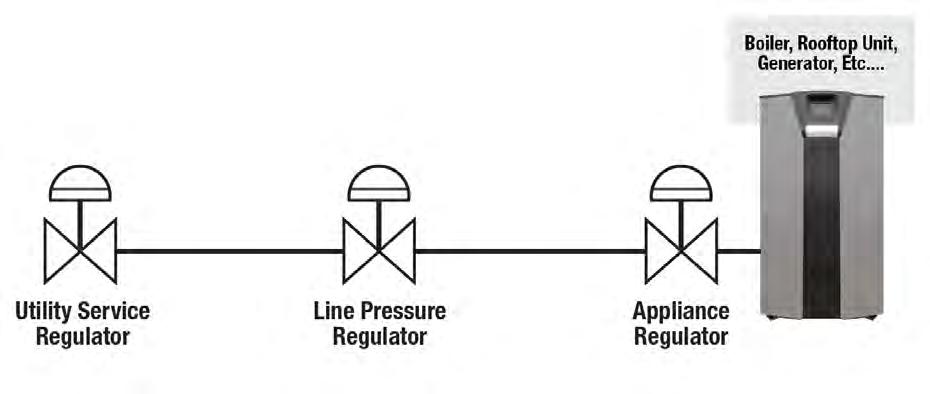
Line pressure regulators are used to reduce the high pressure of gas from the service regulator to a lower pressure that is suitable for the gas appliances. ANSI Z21.80 specifies the test and examination criteria for line pressure regulators, either individual or in combination with over pressure protection devices, intended for application in natural gas piping systems between the service regulator and the gas appliance(s).
The standard applies to regulators rated at 2, 5, or 10 psig with maximum outlet pressure of ½ or 2 psig (depending on the intended application). The standard also covers topics such as design, construction, performance, marking, and installation of line pressure regulators.
As of May 1, 2002, CSA Group requires that all line pressure regulators above 2 psig must leave the factory pre-assembled and leak-tested.
LINE PRESSURE REGULATOR VS APPLIANCE REGULATOR STANDARDS
The current standards for appliance regulators are ANSI Z21.18/CSA 6.3, while line pressure regulator standards are ANSI Z21.80/CSA 6.22.
Historically, appliance regulators were used as line pressure regulators before ANSI Z21.80/CSA 6.22 was developed. With the implementation of the newer and revised standards, appliance regulators should no longer be used as line pressure regulators.
This rule has been confusing given that many longtime favorite appliance regulators were used as line pressure regulators.
ANSI STANDARDS PLAYBOOK
Overpressure protection devices shall be provided to prevent the pressure in the piping system from exceeding that value that would cause unsafe operation of any connected and properly adjusted appliances.
ANSI Z21.80/CSA 6.22
In non-ANSI/CSA applications we can still provide over pressure protection.
PRESSURES FROM 2 TO 10 PSIG REQUIRE AN OPD
Can
Can provide OPD protection using the following: •IRV •Monitor •Slam shut
In non-ANSI/CSA applications, we can still provide over pressure protection
TECHNICAL NOTE
Rules of Thumb and Procedures for Sizing Gas Regulators - Industrial
Sizing Spring Loaded Regulators:
Questions to Ask
What Type of Gas? (Natural or Propane)?
What is Inlet Pressure? (Min and Max if it varies)
What is Outlet Pressure? (set point and or range)
What is Connected Load? (in BTU or CuFt)
Is Regulator Located Inside or Outside?
If Inside, do you want it "ventless"?
What is Line Size?
Is Connected Load a Single Appliance or Multiple & are any high efficiency?
If Inlet Pressure is above 2 PSIG do you need an overpressure protection device (OPD)?
Note: If you get items 1-5 we can make a selection, the other items help refine the selection for the application.
Rules of Thumb
Use MINIMUM inlet pressure expected and MAXIMUM flow required when considering capacity needs
If inlet is 2 PSIG or less select the largest orifice. Above 2 PSIG choose the orifice that can meet or exceed the capacity requirement AND meets the safety requirements for safety (see relief/build up). Above 10 PSIG inlet, select the smallest orifice that meets the capacity and safety requirements
Use maximum WORST CASE inlet pressure expected when considering relief performance.
Choose the LIGHTEST spring available that can meet outlet pressure requirements (i.e. choose set point at upper end of spring range but don't max it out.)
Procedure
Step One:
Step Two: Step Three: Step Four: Size orifice to meet capacity requirements based on the lowest potential inlet pressure
Check Maximum inlet pressure rating for the orifice to make sure it meets MAOP of the system
Check relief build-up pressure using relief curves - based on highest potential inlet pressure. Choose the correct adjustment spring
Exceptions to the "Rules"
When sizing for 2 PSIG inlet and 7-14" w.c. out, we generally use as large an orifice as the regulator will accommodate. This is because a "2 PSIG System" will actually often have only 1-1.5 PSIG at the inlet of the regulator. In addition, code generally does not require any form of over-pressure protection, so there is no safety issue associated with a large orifice selection.
TECHNICAL NOTE
True Lock-Up Regulators
Sizing Spring Loaded Regulators - Questions to Ask
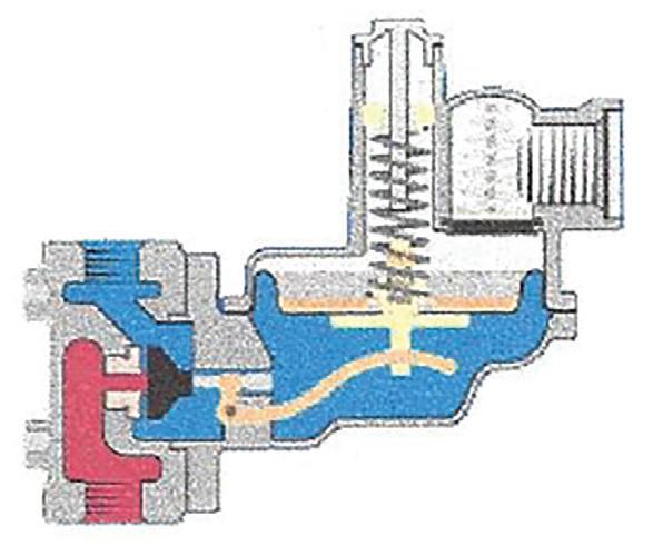
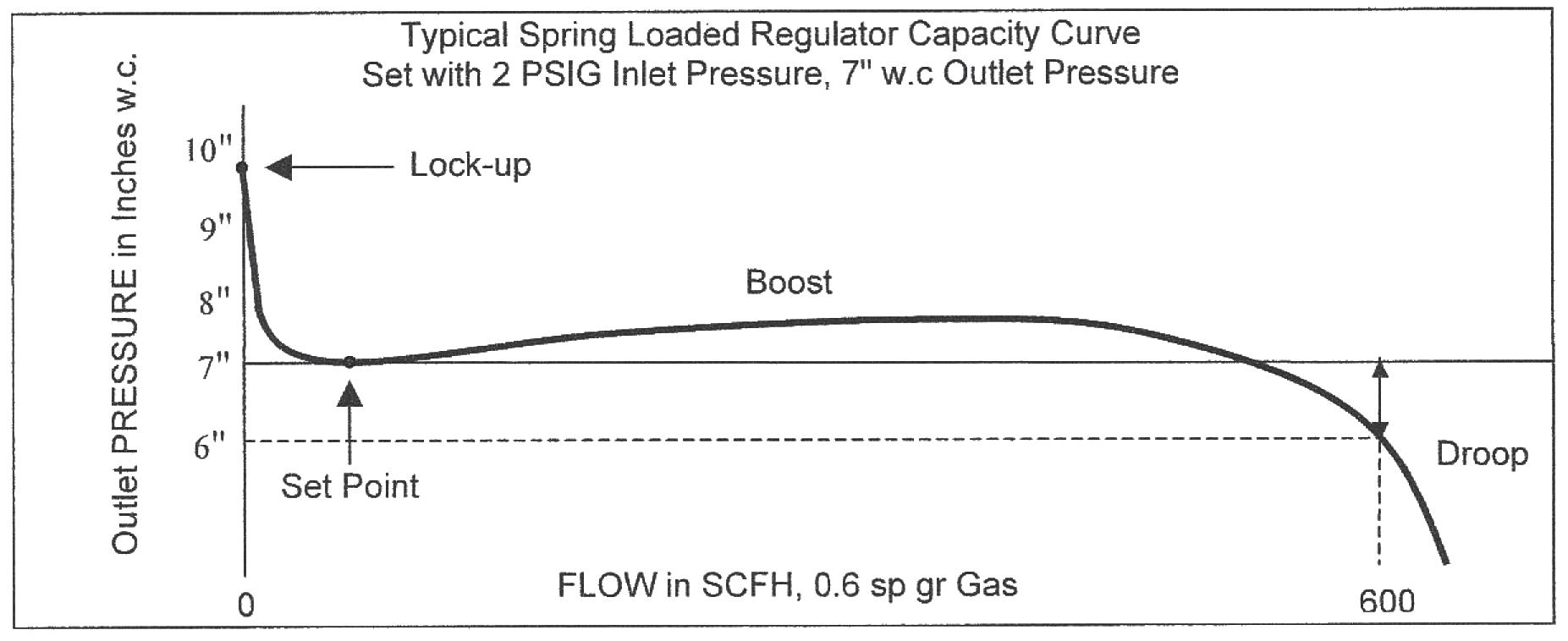
A spring loaded regulator uses a spring on the atmospheric side of the diaphragm to provide an equal and opposite force to the gas pressure that is on the other side of the diaphragm. A regulator is set under flowing conditions at a specific outlet pressure. This is defined as the set pressure. In order for the diaphragm to move down and open the valve, the outlet pressure must drop slightly. This is defined as droop. Inversely, in order to throttle the valve closed, the pressure must rise slightly to overcome the spring force and begin to close the valve. When there is no demand for gas, the pressure will ultimately rise, the valve will close and settle at some pressure above the set point. The state in which there is no-flow and the regulator is closed is defined as lock-up.
Appliance Regulator Lock-up
Many appliance style regulators are non-lock up regulators. These regulators conform to ANSI 21.18. They are typically used for fine tuning pressure and are sometimes referred to as "inches to inches" regulators. They are often installed directly on the gas train of an individual appliance and are used to adjust the final pressure for combustion. There are no specific lock-up requirements within the ANSI Z21.18 Appliance Regulator standard. A feature of many of these style regulators is a metal on metal valve seat. This means that when there is no demand from the appliance, the valve can not shut bubble tight and the pressure will equalize across the valve such that the outlet pressure will equal the inlet pressure. Appliance regulators of this design are consider non-lock regulators. An example of a non lock-up regulator is a Maxitrol RV series. Some appliance regulators are "lock-up type" regulators. This simply means that the under no flow conditions the outlet pressure will settle at some pressure below the inlet pressure. As an example, with 2 PSIG inlet, set at 7" w.c., a Maxitrol 210 series might lock-up at 1 PSIG. This does not meet the more stringent requirements of the Line or Service Regulator specifications (see below).
Line Pressure Regulator Lock-up
Line pressure regulators go in-between the appliance and the service regulator. These regulators conform to ANSI Z21.80. They may feed one or more appliances. A characteristic of all line pressure regulators is a soft valve seat that pushes on a metal orifice, permitting "bubble tight lock up" under no-flow conditions. The ANSI Z21.80 Line Pressure regulator code defines two different performance criteria depending on the classification of the regulator.
TECHNICAL NOTE
Classification
Class I regulator (maximum outlet set pressure of 1⁄2 PSI)
Class II Regulator (maximum outlet set pressure of 2 PSIG)
Examples:
Lock pressure shall not exceed:
150 percent of Initial outlet pressure or the initial outlet pressure + 5" w.c., which ever is greater
150 percent of initial outlet pressure
Class 1 regulator set at 2 PSIG inlet, 7" w.c. should lock up under no-flow conditions at 12" w.c. or less.
Class 2 regulator set at 5 PSIG inlet, 2 PSIG should lock up under no-flow conditions at 3 PSIG or less.
Line pressure regulators that meet the above code requirements are considered "True Lock-up" or "Bubble Tight lock-up" regulators. The Maxitrol 325 series and the Pietro Fiorentini Governor are CSA certified ANSI Z21.80 True Lock-up Line Pressure regulators.
Service Pressure Regulator Lock-up
Service pressure regulators go on the outside of the building. They typically feed line pressure & appliance pressure regulators that are downstream of them. Often the service regulator is the property of the local gas distribution company. Because of the variation of pressure in gas distribution system there is tremendous variety in the design and performance of service regulators. There is no single standard that covers all service regulators. One can however look to ANSI B109.4 for some guidance. This standard covers spring loaded regulators with connection sizes up to 1.25", inlet pressures up to 125 PSIG and outlet pressures up to 14" w.c. Section 5.3.5 of B109.4 covers Lock-up:
"When the demand for flow from the regulator is zero, the flow of the gas should be stopped against the maximum inlet pressure recommended by the manufacturer for the applicable orifice. The outlet pressure under no-flow conditions or lock-up pressure shall not exceed 3.0 inches w.c. (above set point)
At temperatures below 70F, the lock-up pressure will increase as the temperature decreases. The lock-up shall not exceed the relief-valve set point. Performance details pertinent to low-temperature operations shall be made available by the manufacturer.
Lock up shall be demonstrated by maintaining the inlet pressure for a minimum of 10 seconds without any rise in the downstream pressure"
It is interesting to note that B109.4 directly addresses the fact that temperature and time can have an effect on lock-up. Service regulators tend to have the most stringent test and performance requirements.
Summary
The advent of high efficiency equipment and most importantly the wide spread use of spark ignition makes lock-up a critical regulator performance characteristic. Without a standing pilot a regulator must close bubble tight each and every time an appliance turns off. The type of regulator selected (be it appliance, line or service) will determine the standard and base lock-up performance to which the regulator is built. In general Service regulators have the best lock up performance, Line regulators are in the middle and appliance regulators have the worst performance. With that said, many other factors can have an effect on lock-up:
TECHNICAL NOTE
Debris
The most common reason for high lock-up is simply debris lodging on the soft seat of the valve seat and impeding the closure of the valve. Most appliance & line regulators have an inspection plate that can removed, allowing the internals to be cleaned. On service regulators it is normal to find a witness mark on the valve seat - this is from the sharp orifice pushing into the soft rubber seat. Over time this witness mark can get deeper or even get small pieces of dirt lodged into it - leading to higher lock up. Again the diaphragm case can be removed to permit the valve seat to be inspected, cleaned and / or replaced. Consult the trouble shooting guides for individual makes and models for more detail.
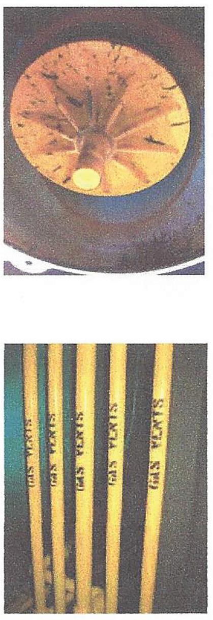
Vents
All regulators have a vent on atmospheric side of the diaphragm. This allows air to move in and out of the diaphragm case as the diaphragm moves up and down to control the flow. As a rule of thumb a vent line should be increased one pipe diameter for 10 effective feet, but in practice this is often not possible As a result, long lengths of vent lines constrict the vent and limit the free flow of air. It is analogous to trying to breath through a 50 foot straw. This can hamper the ability of the regulator to close quickly and thus result in a spike in lock-up pressure. Likewise, some vent limiters can restrict the free flow of air on very fast on/off loads also leading to these momentary spikes.
Fast On Off Appliances
Some high efficiency appliances make use of snap acting solenoids for flow control. This can create line pack (analogous to water hammer). When the downstream valve shuts, the gas is moving as such a high velocity that it packs the line before the regulator can respond and close, resulting in a spike and high lock-up. This issue can be exacerbated if a rotary style meter is in the line. There are a variety of methods to remedy this including:
- Oversizing the regulator to limit the stroke that the regulator has to travel to open and close.
- Converting the regulator from internal sensing to external sensing.
- Increasing the diameter of the downstream piping to limit piping velocities.
- Moving the regulator further from the appliance to create a reservoir to absorb the line pack.
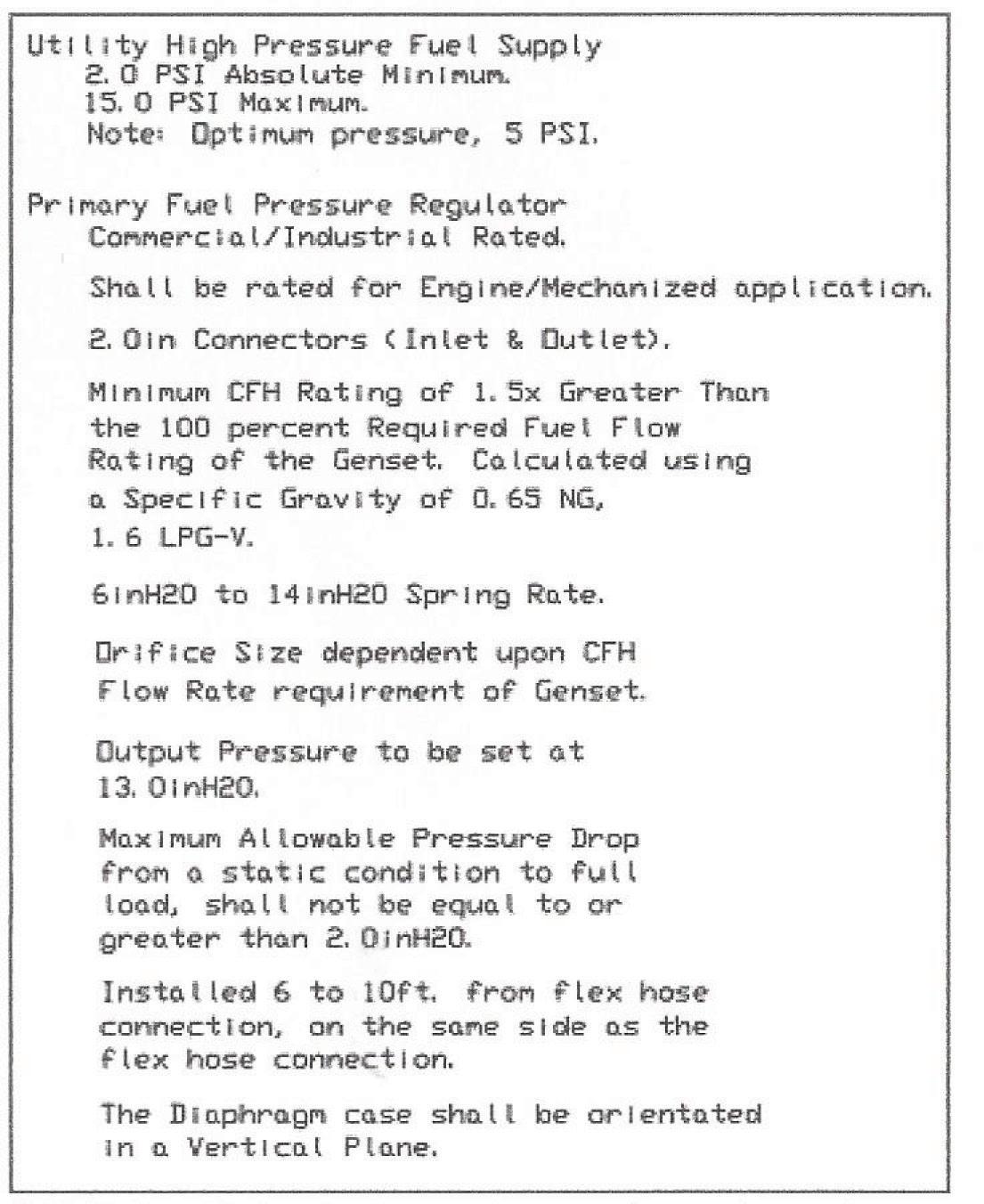
Generators require very specific regulator selection and installation guidelines to function properly. Certain high efficiency boilers such as CAMUS, Lochinvar and Fulton also have specific sizing requirements. Consult out technical notes on best practices for generator and high efficiency boiler installation.
Time & Temperature
Without a standing pilot, the pipe between the regulator and the appliances is in effect a closed pressure vessel. If long lengths of pipe run across a roof (exposed to the sun) or under the ceiling of a boiler room (exposed to the heat of a boiler), the temperature of the gas will rise. This leads to a steady increase in lock-up pressure over time. Pipe exposed to the sun should be painted yellow or silver to reflect the sun's rays. In some cases it may be necessary to add a relief valve or a second regulator.
TECHNICAL NOTE
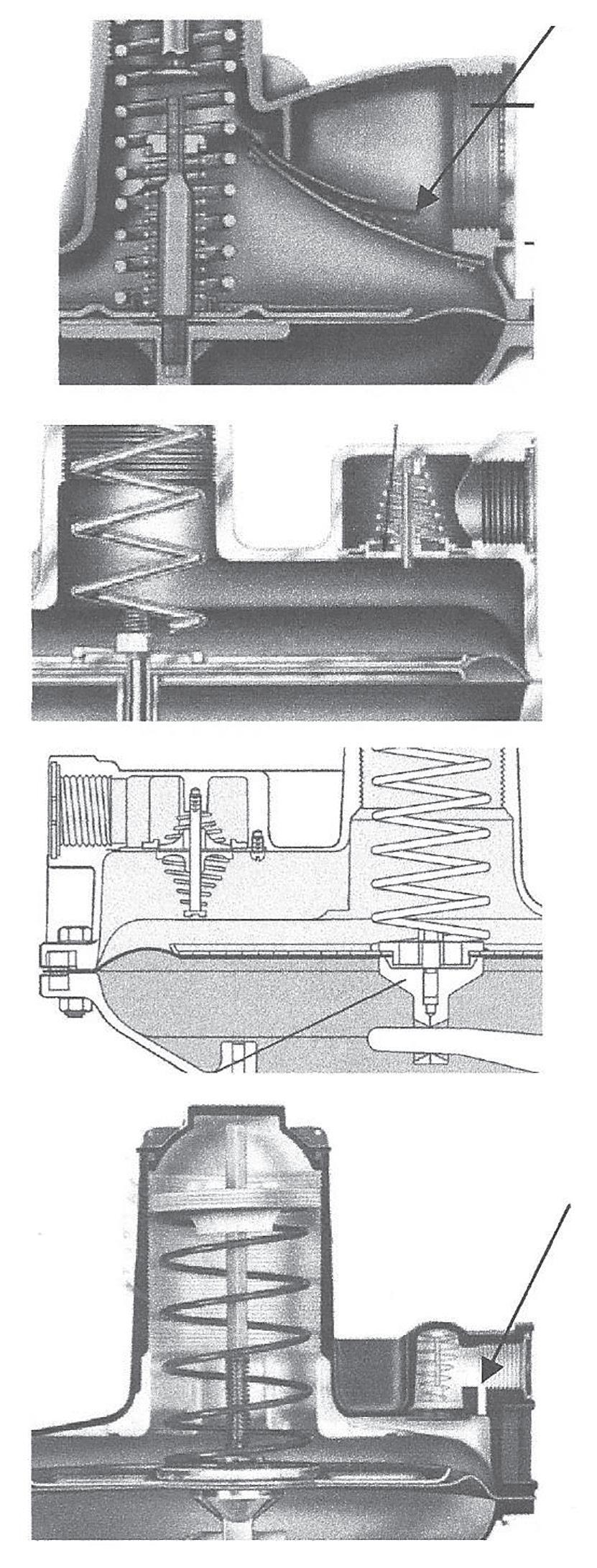
To the left an example of a boiler manufacturer's lock-up requirement that is nearly impossible to meet. To the right an example of a Generator manufacturer's regulator specifications.
This document referred to the following codes and standards:
ANSI Z21.18-2000/CSA 6.3-2000
Addenda 1: ANSI Z21.18a-2001
Addenda 2: ANSI Z21.18b-2005/CSA 6.3b-2005
ANSI Z21.80-2003/CSA 6.22-2003
Addenda 1: ANSI Z21.80a-2005/CSA 6.22a-2005
Gas Appliance Pressure Regulators. Details test and examination criteria for gas appliance pressure regulators for use with natural, manufactured and mixed gases, liquefied petroleum gases and LP gas-air mixtures. Such devices, either individual or in combination with other controls, are intended to control selected outlet gas pressures to individual gas appliances.
Line Pressure Regulators. Details test and examination criteria for line pressure regulators, either individual or in combination with over pressure protection devices intended for application in natural gas piping systems between the service regulator and the gas appliance(s). This standard applies to regulators rated at 2, 5, or 10 psi with maximum outlet pressure of << or = 2 psi, depending on the intended application.
TECHNICAL NOTE
ANSI B109.4-98
AGA/GAMA X-50865*
Self-Operated Diaphragm Type Natural Gas Service Regulators A basic standard for the safe and reliable operation, and the substantial and durable construction of self-operated diaphragm type natural gas service regulators, for nominal pipe size of 1-1/4 inches and smaller with outlet pressure of 14 inch water column or less. Pertains to cast iron or alu. regulators, (w/ no external sensing lines) at operating pressures up to 125 PSIG, with the following characteristics: Removable valve orifice, valve disk of resilient material. May also incorporate an IRV capable of limiting downstream pressure to 2 PSIG in event of wide open failure.
Service Regulator Specifications. These specifications were prepared by the Task Committee on Service Type Regulators, comprised of members of AGA (District Operating Section) & GAMA (Meter & Regulator Div.). They establish specifications for (1) materials, strengths and operating characteristics for service type regulators, (2) standard methods of testing and reporting testing (3) allowing freedom for introduction of new materials, designs and technology in the manufacture of Service Type Regulators. Apply to Pounds to inches style regulators, sizes 2" and smaller. Applicable to regulators with the following characteristics: (A) capable of reducing Pounds to inches, (B) Single valve orifice, (C) Valve disc made of resilient material (D) self contained, no external control lines
CSA 6.18-02 (CAN/CGA6.18-M91)
NFPA 54/ ANSI Z223.1
UL144
Service Regulators for Natural Gas. These provisions apply to the construction, materials, performance, and testing of NPS 1-1/4 in and smaller self-acting service-type regulators with internal relief valves or overpressure cut-off (OPCO)* devices, or both, utilized to control the pressure of gas delivered to a customer's piping at a delivery pressure of 5 to 9 in water column (1.24 to 2.24 kPa), for installations designed for capacities up to 250 SCFH (7.1 m3/h). *Overpressure cut-off (OPCO) devices are also referred to as overpressure shut-off (OPSO) devices.
National Fuel Gas Code. Provides safety requirements for the design and installation of fuel gas piping systems in homes and other buildings.
Standard for Pressure Regulating Valves for LP-Gas. Regulators covered by these requirements are intended for non-refrigerated systems in accordance with NFPA 58, NFPA 54, AGA Z21.58 and NFPA 501C. Covers Low Pressure LP-Gas Regulators defined as reducing cylinder pressure (gaseous phase only) in excess of 1 PSIG to an outlet pressure of 1 PSIG or less. Second stage service of 20 PSIG inlet or less. High Pressure regulators are defined as being capable of handling gaseous or liquid phases. The standard defines construction, performance, testing and marking.
TECHNICAL NOTE
Regulator Vents and Effects on Fast On/Off Loads
Vent design and vent piping can have a dramatic effect on regulator performance. On fast on loads, the regulator diaphragm drops in conjunction with the drop in pressure in the downstream piping as the appliance turns on and consumes gas. As the diaphragm moves downward, air must move into the upper diaphragm case and is pulled through the vent. The vent is normally associated with the internal relief valve, but under normal operation the regulator breaths through the vent as the diaphragm moves up and down responding to pressure and flow fluctuations. Most regulators have a relatively large vent that is sized for the internal relief valve. Normal breathing however requires fairly little surface area so a flapper is employed to keep debris out of the regulator and provide a certain degree of dampening. If the vent flapper is completely removed the regulator may become unstable and pulsate. If the vent flapper is held in place (either by debris or ice) the regulator becomes sluggish and slow to respond. Each manufacture employs a slightly different design to permit the optimal combination of breathing, dampening and relief capacity.
The American meter 1800 series employs a large square rubber flapper that is hinged on the top side and held in place with a relatively stiff wire clip. It has a large surface area for relief. Breathing-in during fast on operation is accomplished by air simply being drawn past the edges of the flapper.
The Sensus/Invensys/Equimeter/Rockwell 243 series uses a round 2 way vent valve, the flapper disc is held in place with a set of light springs and rides on a stainless steel shaft. The two way design permits fast response to rapid changing loads.
Fisher 200 series
The Fisher 200 series employs a round stabilizer vent with a set of opposing springs riding on a stainless steel shaft. This design permits bi-direction dampened breathing.
The Sprague/Schlumberger/Actaris B34 and B38 series uses a round plastic vent disc that is held in place with a conical vent spring and rides on a stainless steel shaft. 2 different vent springs (standard and extra heavy) are available to permit different degrees of dampening. On the 34 series (SR, R and IM) a #10 breathing hole is drilled through the vent into the upper diaphragm case (pictured to right). Inserts (#32, # 44 and solid) permit this hole to be reduced for dampening effect. On the 38 series the breathing #10 hole is actually drilled in the vent disc. Both regulators also have a loading ring in the body of the regulator. The load ring can also be used to increase speed of response (for fast on loads) or reduce the sensitivity of the regulator (in the event of pulsations).
Flapper
Breather Hole
TECHNICAL NOTE
Commentary on Overpressure Protection
An overpressure protection device is something that protects the downstream piping from an unsafe pressure build-up in the event that the regulator fails. Typically a regulator fails when debris builds up on the valve seat or orifice. This keeps the regulator from locking up (shutting bubble tight) during periods when there is no gas usage. As a result, gas will continue to pass through the regulator and the pressure will build up in the downstream piping.
As an example, a regulator with 5 PSIG on the inlet, set to deliver 7" w.c. should normally lock up at under 12" w.c. If debris kept the valve open, the pressure could potentially rise as high as 5 PSIG. Since many appliance valves and regulators are only rated with a 14" w.c. Operating and 2 PSIG Emergency pressure rating, they may not function properly or may be damaged causing potential unsafe operation.
A variety of Overpressure Protection Devices (OPD) exist including:
Spring Loaded Relief Device (Relief Valve)
Monitor Regulators
A Series Regulator (2 stage cut)
Automatic Shutoff Device with manual reset
These can be an integral part of the regulator or a separate unit.
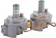
Examples
Regulators with Internal Relief Valves External Relief Valves Internal Monitors
Operator Monitor Sets 2 stage cuts
Slam Shuts
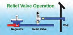
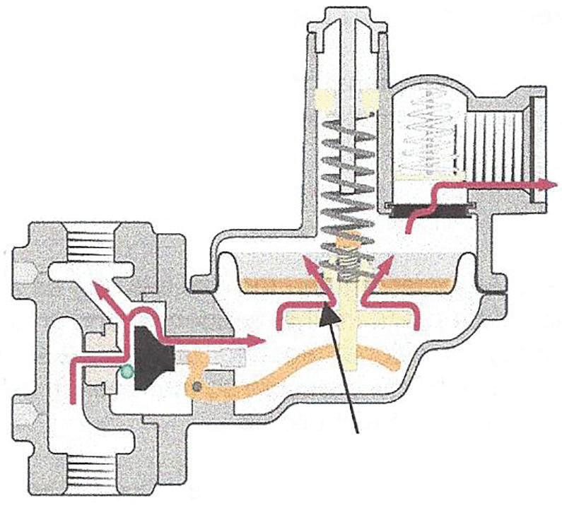
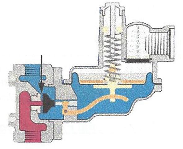
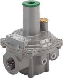
The service regulator above is built with an internal relief valve. If the regulator is properly sized and selected the relief valve can provide overpressure protection and be used in 2 PSIG or 5 PSIG systems. This type of regulator must always be vented to a safe outside location.
Should be able to close or "lock-up" bubble tight here
The line pressure regulator above does not have an OPD (over-pressure protection device) built into it. For CSA compliant systems, this regulator should only be used on inlet pressures of 2 PSIG or less and outlet pressures of 14" w.c.or less.
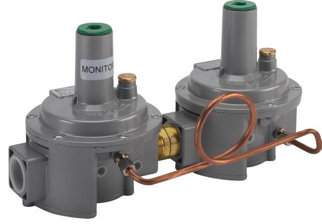
The line pressure regulator above employs an upstream wide open monitor. It senses the pressure being delivered by the downstream regulator. Should the downstream regulator fail open, the upstream monitor takes over and maintains pressure close to set point. This type of regulator is CSA certified for installation on systems up to 5 PSIG inlet and can be installed without a vent line if local authorities permit.
TECHNICAL NOTE
Overpressure protection is required by code in most installations where pressure is 2 PSIG. Below are excerpts from most relevant codes.
NFPA 54 / ANSI Z223.1 National Fuel Gas Code
General. Overpressure protection devices shall be provided to prevent the pressure in the piping system from exceeding that value that would be cause unsafe operation of any connected and properly adjusted appliance.[see 5.9.5]
5.9.5
Each pressure limiting or pressure relieving device shall be set so that the pressure shall not exceed a safe level beyond the maximum allowable working pressure for the piping and appliances connected.
International
416 (IFGS)
Fuel
Gas Code
General. Overpressure protection devices shall be provided in accordance with this section to prevent the pressure in the piping system from exceeding the pressure that would cause unsafe operation of any connected and properly adjusted appliance.
IFGS Commentary: "Overpressure protection devices are used to protect appliances from abnormally high gas pressure that can result from the failure of pressure regulators in the piping system. Overpressure could result in appliance damage and/or hazardous operation (see commentary section 410.1)
ANSI Z21.80 / CSA 6.22-M97 Standard for Line Pressure Regulators
Overpressure Protection Devices
Line Pressure regulators rated for inlet pressures in excess of 2 PSI (13.8 kPa) and capable of being adjusted to deliver an outlet pressure of 1⁄2 PSI (3.5 kPa) or less shall be provided with an independent means to limit the downstream pressure to 2 PSI (13.8 kPa) maximum in the event of failure of the regulating mechanism.
An overpressure shutoff device (see part V, Definitions), if provided, shall require a manual procedure to reset the device following actuation 1.14.2
Author's Comments:
Within GAMA (the Gas Appliance Manufacturer's Association) and the gas industry as a whole, it has generally been accepted that the acceptable safe pressure that residential and small commercial systems can accept under emergency conditions (regulator failure) is 2 PSIG. Most gas utilities will size their Service Regulators that deliver low pressure so that even in a failed state they will limit the downstream piping pressure to 2 PSIG build up.
Most gas valves are only rated for 14" w.c. (0.5 PSIG) Operating Pressure. Due to the fact that many gas appliances now lack standing pilots, the gas pressure can continue to rise after the appliance shuts off. This static pressure is gray zone because the appliance is not running (operating) but will be subject to this elevated pressure for a split second when it next turns on. There is much debate about what pressure these devices can handle at static and still operate. Likewise, when an upstream regulator fails the pressure will rise irrespective of whether over- pressure protection is employed. It is still clear that above 2 PSIG some form of over-pressure protection is required.
TECHNICAL NOTE
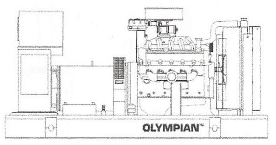
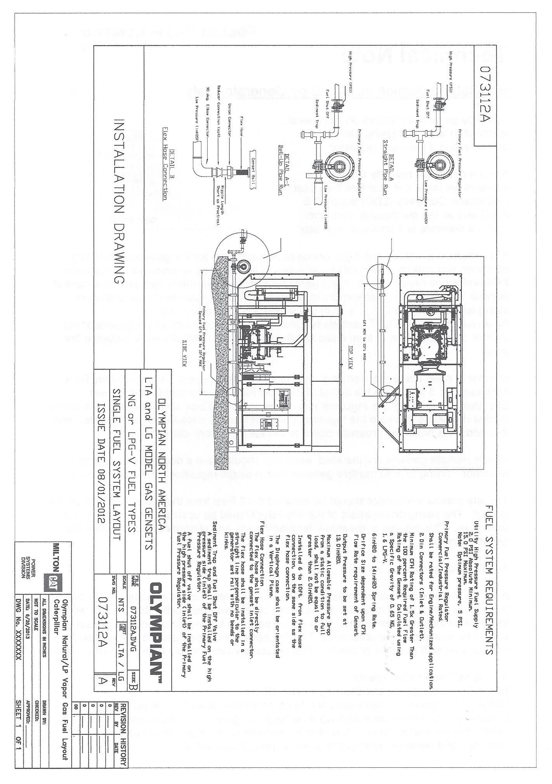
Regulator Selection for Stand-by Generator Sets
Stand-by generators require an extra level of attention when designing fuel piping and selecting a pressure regulator.
Since a generator typically requires elevated pressure it is best that the Local Distribution Company (LDC) supply 2-5 PSIG and let the mechanical contractor install a separate line pressure regulator.
It is important to establish the gas pressure requirements for the generator including minimum and maximum allowable pressures as well as lock up pressure. Because of EPA emissions requirements, many generators require extremely tight pressure control. Normal regulator sizing techniques must be modified because most manufacturers sizing tables are based on 2" w.c. of droop and 3-5" w.c. of lock-up.
As an example, some CAT gensets require that the fuel pressure of the generator not deviate more than 2" w.c. from static to full load. This includes pressure losses in the pipe.
In order to meet these requirements, the line pressure regulator should be sized for a minimum of 1.5 to 2 times the actual 100% Fuel Flow requirement for the genset. Effectively "oversizing" the regulator minimizes droop and lock-up associated with spring loaded regulators because the regulator does not need to stroke open as much to meet demand. This holds the pressure closer to the set point from idle to full load
Where multiple gensets are installed, each one should have a dedicated line pressure regulator. Trying to feed multiple gensets from a single regulator can be problematic.
The line pressure regulator should be installed 6-10 Feet from the fuel connection on the genset. The piping downstream of the regulator should be upsized (belled-up) by 1-2 pipe sizes. This creates a "reservoir" for black starts and absorbs line pack when the genset turns off.
Addition piping considerations:
A1⁄4" pressure tap should be installed 2-4 feet downstream of the regulator. This permits a pressure gauge to be installed; in the event of regulator instability, this tap can be used to install an external control line. The piping between the regulator and the genset should be straight and unobstructed. The flex hose should be installed perpendicular to the gas inlet with no kinks or bends. Inlet pressure valves should be full port ball valves.
Additional code requirements:
NFPA 110, Emergency and Standby Power, Section 5-9:
NFPA 110 requires the fuel supply line to be connected ahead of the building's main shutoff valve & marked as supplying an emergency generator. The building's main gas valve must be marked to alert first responders/maintenance personnel as to the presence of a separate emergency power supply shutoff valve.