Ravenna Plant - Via del Bragozzo, 7, 48122 Ravenna (RA) +39 0544 436438 - eos@donelli.it
Parlare di anima ci sembra profondamente coerente perché è appunto questo che troverete nelle nostre cinque sedi...
donelli.it
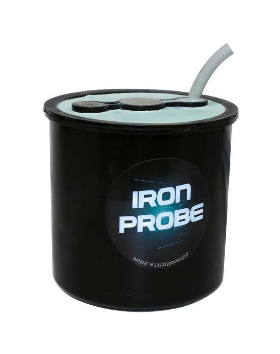
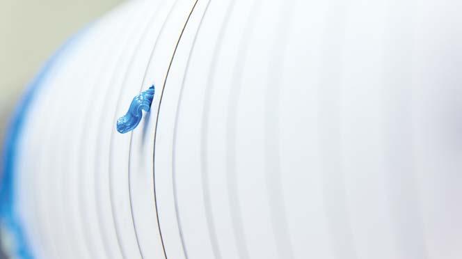
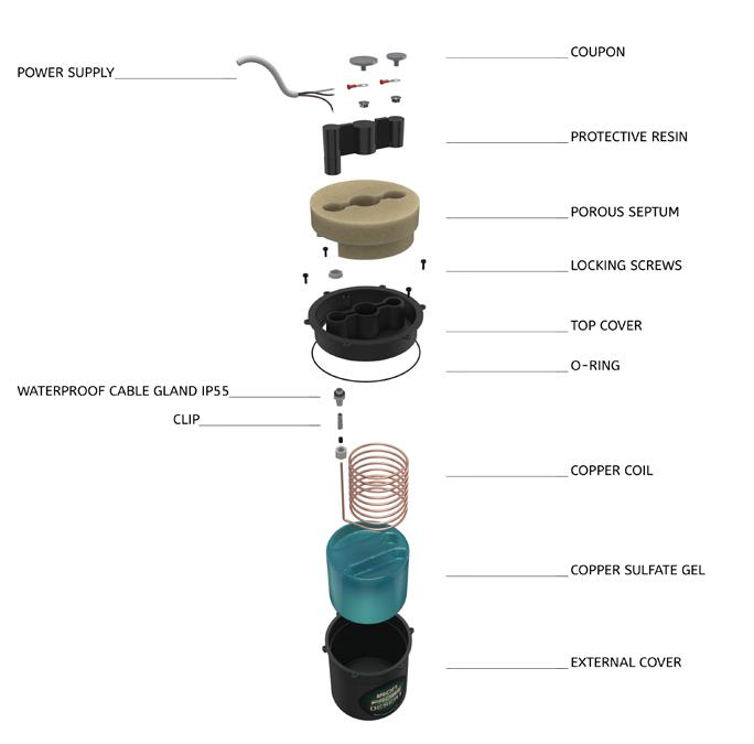
The new patented reference electrode with high conductivity and hygroscopic
Recycled polyoxymethylene
Patented ceramic mesh with high conductivity and hygroscopic power with a contact surface of 117,5 cm2
Patented Copper Sulfate Mixture (CSM) no sulphate leakage for capillarity
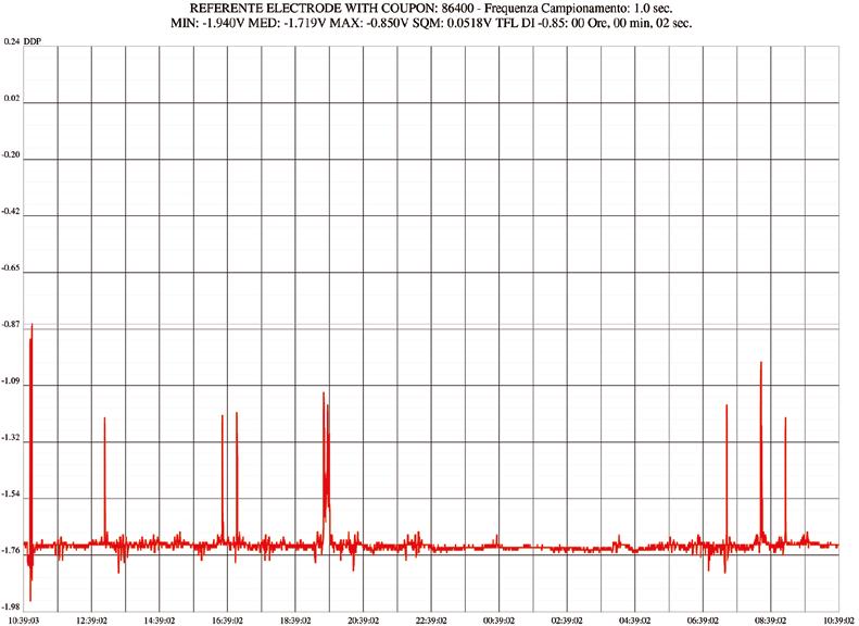
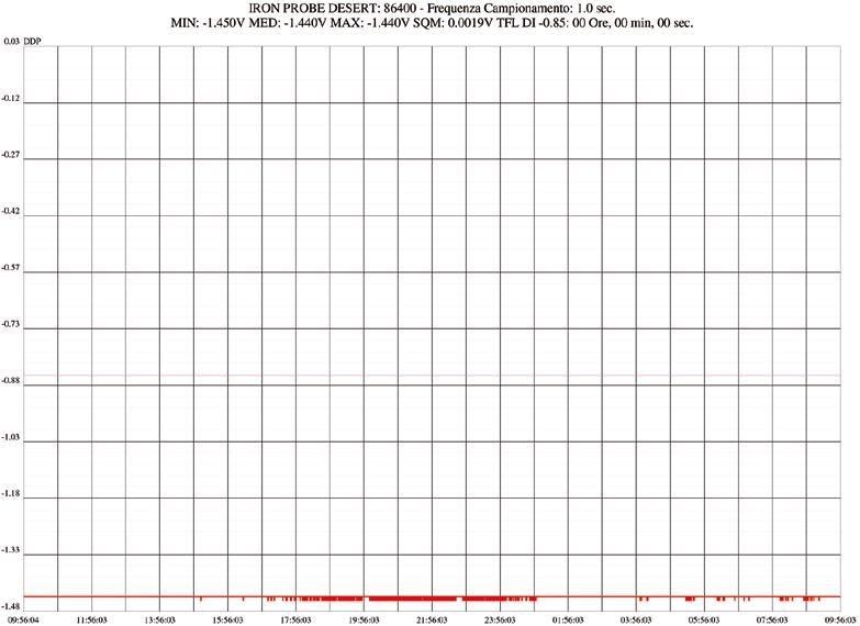
Improved stability especially on high resistivity soils
10 cm2 carbon steel coupon for DC and 5 cm2 for AC
Minimum distance between porous septum and coupon 7 mm
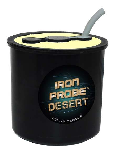
Registered European trademark and patent no. 202022000002267
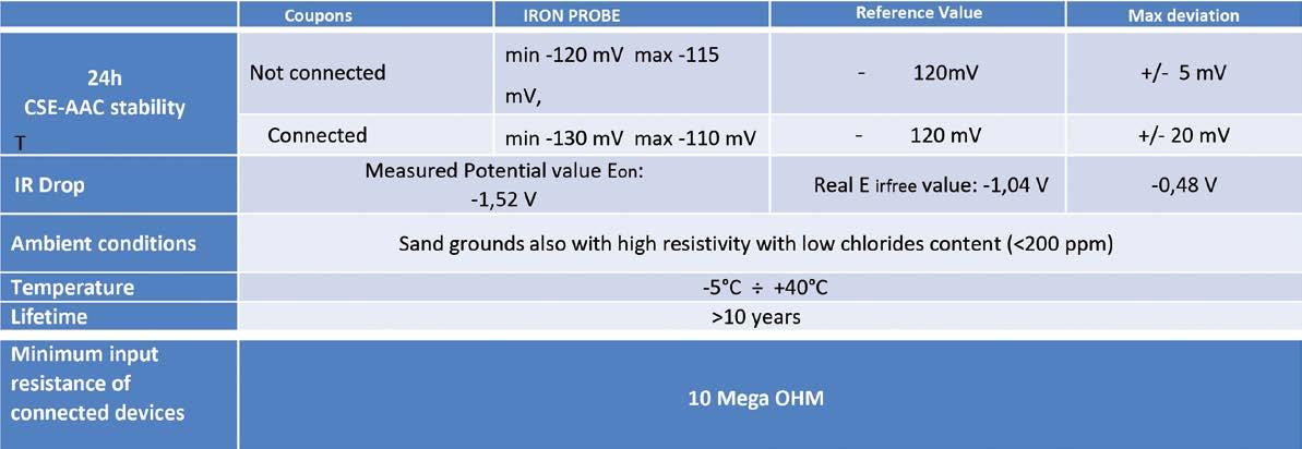
Accordingly to EN ISO 15589-1
Patented ceramic mesh with high conductivity and hygroscopic power with a contact surface of 117.5 cm designed for sandy and highly resistant soils (for type DESERT)
14
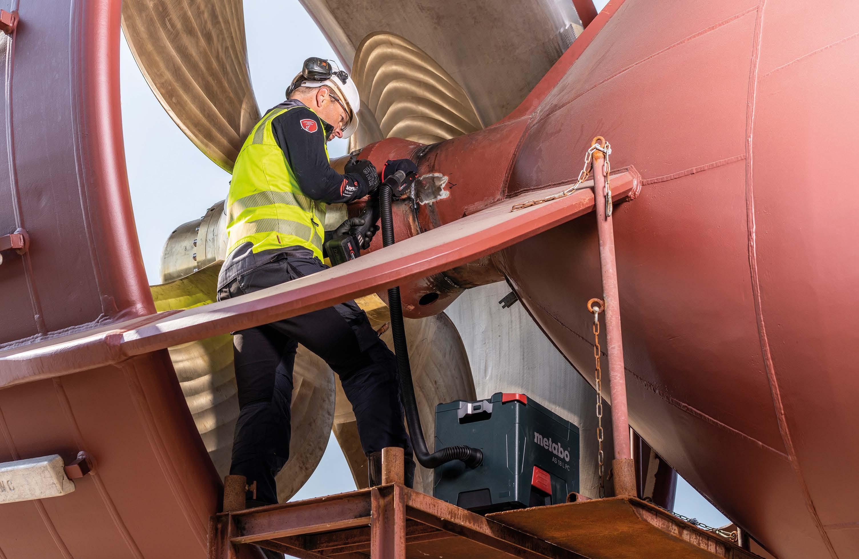
SmartPad System vs corrosion under pipe supports
20 ROAD TO 2050
Offshore wind sector must unite to future-proof renewable energy investment
22 SPOTLIGHT
Restoring steel with a gentle touch: why bristle blasting is a smart alternative for grit blasting before coating
28 SCIENCE OUTLOOK
Prevention of the stiction phenomenon of automotive braking systems
34 ROAD TO 2050
CIN Performance Coatings: coatings for a more sustainable future
36 SUCCESS STORY
Jotun and Messina signs impactful Hull Skating Solutions agreement
38 SPOTLIGHT
Corrosion concerns in vehicle exports via sea route from Asia: causes, risks and solutions
42 COVER STORY
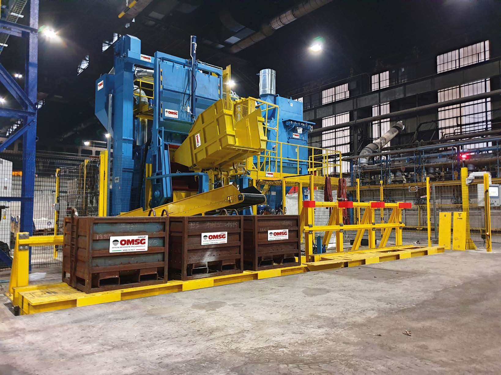
A mechanical department integrated with high-efficiency shot blasting systems: LTC’s choice to ensure the durability of its magnetic cores
50 SUCCESS STORY
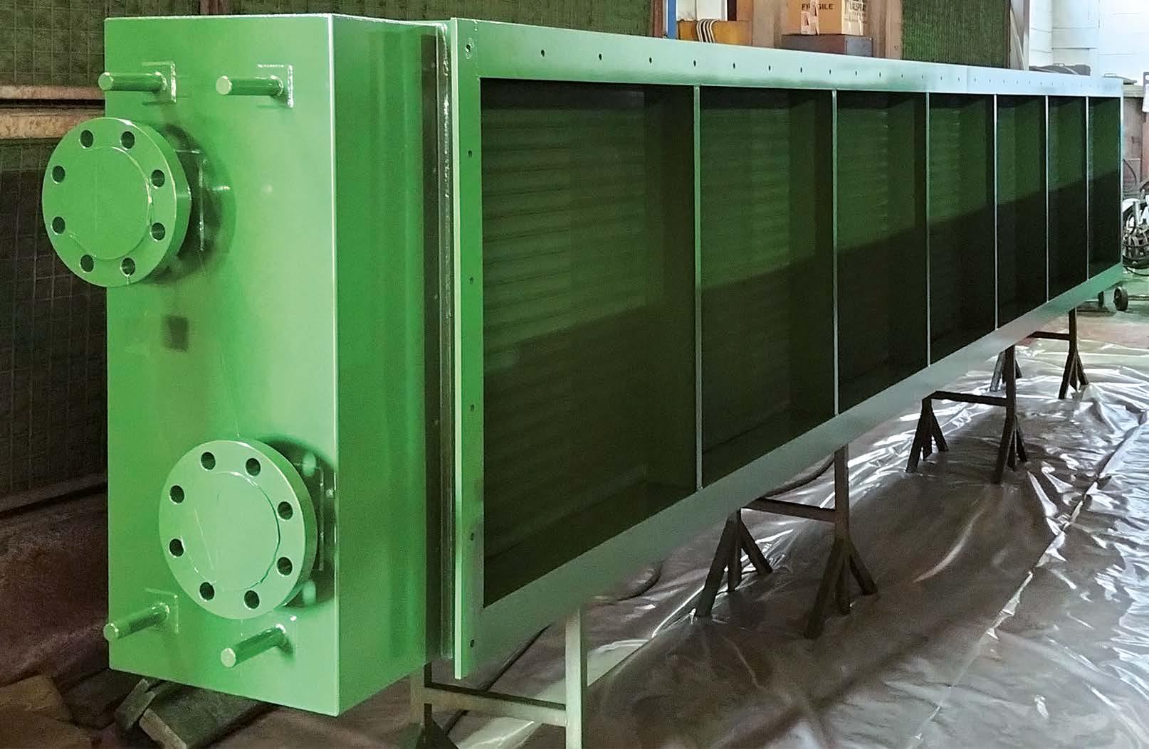
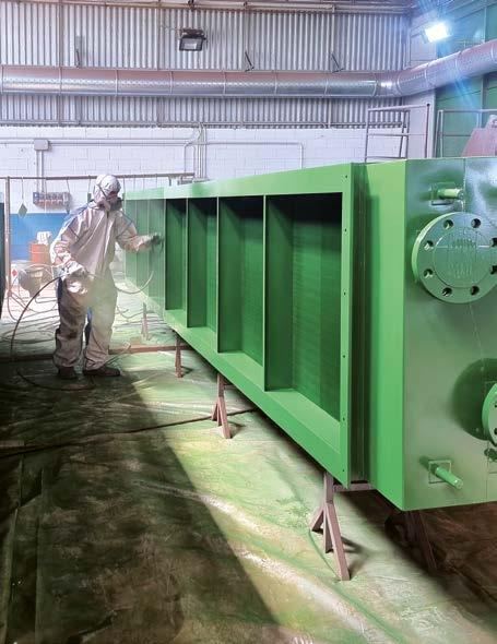
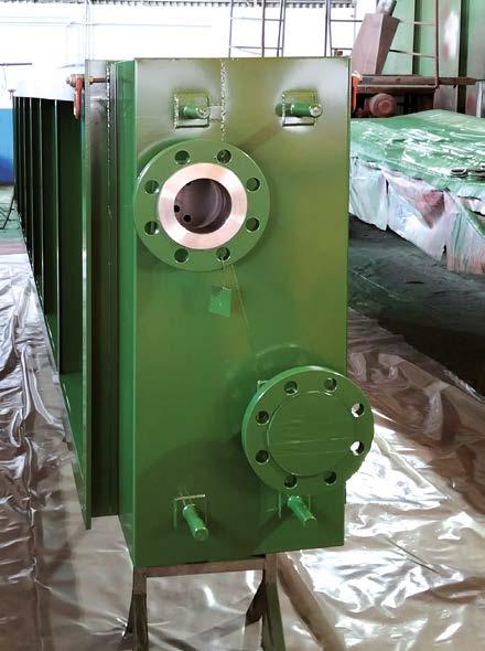
Säkaphen and Donelli: joining forces for heat exchanger protection
52 ADVANCEMENTS
Visco-elastic technology: a monolithic, amorphous coating transforming pipeline protection
58 SCIENCE OUTLOOK
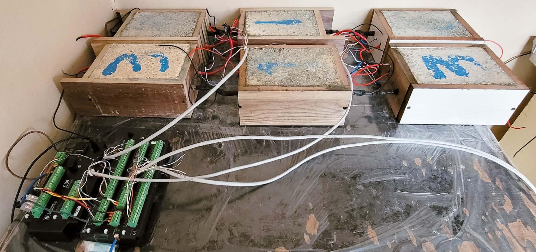
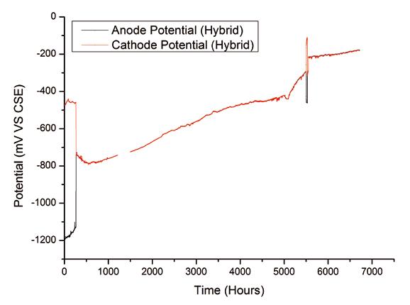
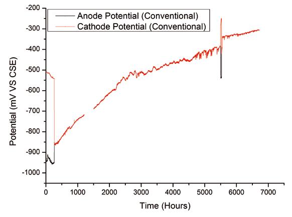
New generation of galvanic anodes for cathodic protection of concrete structures
66 ADVANCEMENTS
IRON PROBE DESERT: a new, patented probe for high-resistivity soils
72 CORROSION INSIGHTS
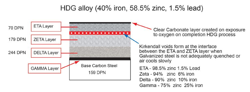
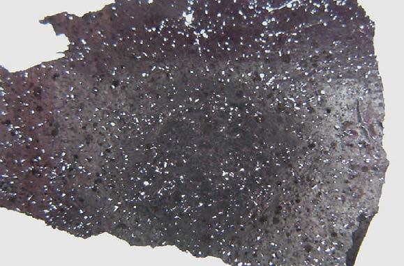
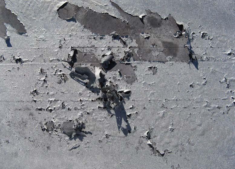
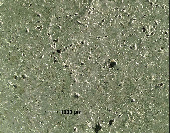
Duplex coating failures associated with galvanised structures
EDITOR FROM THE
Alessia Venturi
Editor-in-chief
The most advanced solutions arise at the intersection of different disciplines, where knowledge of electrochemical phenomena merges with data intelligence. Today, smart sensors can detect minimal variations in humidity, temperature, or electrical potential and, thanks to AI, translate this data into predictive models that anticipate the risk of corrosion.
Sustainability does not begin with renewable energy or recycled materials, but with something more subtle and concrete: the protection of metal against corrosion. Extending the service life of industrial assets, infrastructure, and metal components is the first and often the most effective weapon for reducing environmental impact, as well as production and maintenance costs. Every year, corrosion generates enormous economic losses and a wasteful use of resources. Preventing it means not only saving money but also avoiding the need to produce, transport, and dispose of new materials.
As you will notice in the following pages of this Corrosion Protection issue, which focuses on cathodic protection, interdisciplinary collaboration is one of the keys to developing new protective and maintenance technologies. Metal protection is no longer confined to materials engineering or coating chemistry: today, it also involves physicists, data scientists, sensor experts, computer scientists, and environmental engineers. Only when combining these skills is it possible to develop technologies capable of predicting, monitoring, and counteracting material degradation accurately and promptly.
The most advanced solutions arise at the intersection of different disciplines, where knowledge of electrochemical phenomena merges with data intelligence. Today, smart sensors can detect minimal variations in humidity, temperature, or electrical potential and, thanks to AI, translate this data into predictive models that anticipate the risk of corrosion.
This results in truly preventive maintenance, which dramatically reduces plant downtime and intervention costs while improving safety and operational continuity. These two aspects are key to detecting and assessing corrosion, but also to developing prevention systems that are increasingly accessible and practical.
For example, inorganic but non-metallic protection technologies that can be installed in a matter of minutes and with little effort and cleaning and surface preparation systems that do not require complex infrastructure for their management – often impossible to install in sites such as offshore platforms or shipyards – are the future. This and much more is covered in the latest issue of Corrosion Protection for this year. It is packed with international content, sourced from both prestigious research institutes and companies conducting research in emerging economies such as India, also demonstrating the increasingly global reach and appeal of this technical and scientific journal.
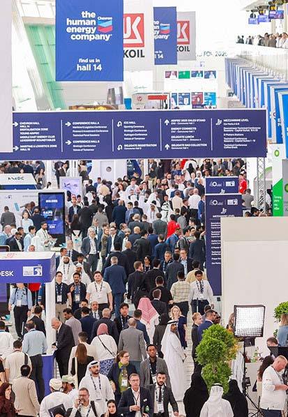
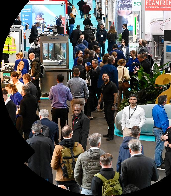
Among the many trade fairs we will be attending to distribute it is ADIPEC, held in Abu Dhabi in November: with 17 exhibition halls and over 2,250 exhibitors, the world’s largest energy-related event will also focus on corrosion protection – because extending the life of materials means extending the life of infrastructure.
After all, sustainability is not just a matter of new materials, but of intelligence applied to those we already have.
NEW WHAT’S
Sherwin-Williams launches lowest total applied cost coatings platform for rail cars
Sherwin-Williams Protective & Marine is delivering notable cost-saving efficiencies to the rail car market with the launch of three new water-based coatings under its time-tested CarClad® platform. The new line of water-based acrylics offers the lowest total applied cost for coating rail cars based on the durability and long service life of the coatings, as well as their application efficiencies. The line includes: CarClad® WB 2600, a direct-tometal or two-coat exterior topcoat; CarClad® WB 1400, an anticorrosive primer; and CarClad® 600, a fast-drying coating for carbon steel jacketed car interiors and tank car exteriors.
“When developing our new line of water-based CarClad WB coatings, we wanted to create a platform that can deliver the lowest total cost of ownership on the market,” said Taylor Lewis, Sales Director – Freight Rail, Sherwin-Williams Protective & Marine. “That meant focusing on longevity of service, so cars can stay on the tracks and out of the coatings shop. It also meant ensuring shop applications can be completed as efficiently as possible, so cars can get back into service quickly. We’ve achieved both goals and more with the new CarClad WB offerings.”
The water-based acrylic CarClad WB coatings rival the longterm performance of traditional solvent-based epoxy coatings, providing corrosion protection, durability, excellent adhesion, chemical resistance, extended service life and reduced maintenance needs. For example, CarClad WB 2600 applied to a general freight car operating in non-corrosive environments is expected to last 15 to 20 years before a recoat is required. The coating’s flexibility helps with that longevity, as it can withstand impacts and hammering from aggressive loading and unloading without fracturing, which can happen with epoxies. In addition, the acrylic CarClad WB coatings offer excellent colour and gloss retention, allowing owners to keep cars in operation longer without worrying about aesthetics.
The higher volume solids nature of the coatings also offers additional durability, as well as sustainability. CarClad WB solutions feature 40% volume solids – a high volume compared to most coatings in this category, which typically contain just 32-35% volume solids. The additional solids promote edge retention and durability, as more of the coating material remains on sharp corners and flat surfaces after curing. With higher volume solids content, the CarClad WB coatings also release fewer volatile organic compounds (VOCs) when curing, reducing their environmental impacts compared to lower volume solids formulations.
Even the coating formulation itself is friendly to applicators, as it contains no chemicals or oils that are known to cause sensitization.
The three CarClad WB coatings are designed for ease of application and fast shop throughput. Each formulation dries quickly, allowing shops to apply stenciling shortly after applications and rapidly move completed cars off the line to enable quick returns to service. In most cases, CarClad WB 2600 is applied direct-to-metal in a single pass with no primer needed. The coating can be applied up to 10 to 12 mils dry film thickness in a single coat. While it dries quickly, the coating stays wet long enough to minimize the potential of creating a bumpy dry spray finish as crewmembers overspray each other’s work during applications. CarClad WB 2600 also allows for both lowertemperature and moisture-resistant applications, providing flexibility and efficiencies for shops based in different climates. Applicators may use the CarClad WB 1400 primer when greater corrosion protection and durability are required, as well as to avoid flash rusting when steel components are to be staged for future assembly. For enhanced efficiency when using a two-coat system, they can apply the topcoat in a wet-on-wet application about 30 minutes after applying the primer.
For maintenance applications, the recoat window for the CarClad WB coatings is unlimited, allowing owners to perform easy touch-ups whenever required.
“Adding these versatile water-based acrylics to our comprehensive portfolio of rail car coatings and augmenting their performance enhances our ability to provide full service to the market and get them what they need when they need it,” said Lewis. “Coupling those capabilities with our domestic and international manufacturing capabilities, plus our well-established distribution channel, enables us to be a one-stop shop with a short supply chain for coating hopper cars, tank cars, gondolas, box cars, flat cars, autoracks and a wide variety of intermodal cars and containers.”
http://protective.sherwin-williams.com
PPG underscores critical role of accurate fire testing in passive fire protection
PPG announced the publication of a white paper1 exploring the crucial role that passive fire protection (PFP) testing plays in preserving the structural integrity of steel when fires occur in commercial and industrial buildings. The white paper, ‘Understanding Fire Testing Practices for Cellulosic Passive Fire Protection Systems: A Critical Component of Structural Safety’, emphasizes that accurate fire testing and compliance with industry standards are essential to ensure the reliability of PFP coatings. Variations in application thickness, building loads and environmental conditions can significantly impact performance; since malfunctioning products could put lives at risk, verifiable and reproducible test results are paramount. "With evolving regulations and increasingly complex building codes, it is imperative that PFP systems undergo rigorous, accurate standardized fire testing to help ensure reliable performance," said Richard Mann, PPG global product manager, passive fire protection, Protective and Marine Coatings. “We are committed to providing superior fire protection solutions and adhering to internationally recognized testing processes to remain a trusted coatings partner in the field.”
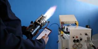
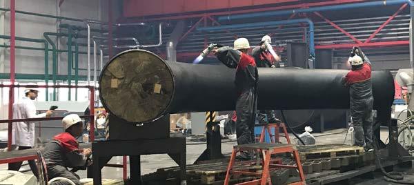
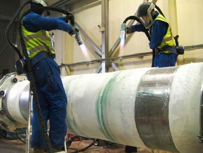
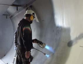
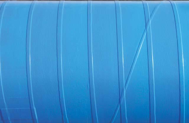
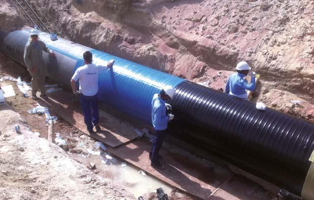
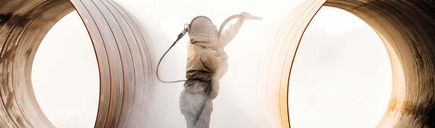
IBIX SURFACE PREPARATION AND FLAME SPRAY TECHNOLOGY
for long-term anti-corrosion and waterproofing thermoplastic coatings
Key topics covered in the white paper include:
An overview of intumescent PFP coating technologies, including PPG STEELGUARD ® solutions
Comparisons of fire testing standards (UL 263, ASTM E119, EN 13381-8, GB 14907)
Testing protocols for restrained and unrestrained steel sections and assemblies
The impact of system compatibility on fire protection performance, including the role of primers and topcoats
Best practices to ensure compliance with the International Building Code (IBC) and other regulations.
PPG utilizes in-house facilities, such as its dedicated UL-certified Global Fire Protection Technology Center and extensive thirdparty testing to develop products that meet and exceed global fire protection standards while also delivering operational advantages and appealing aesthetic finishes. The PPG PFP team has decades of experience working in the fire protection industry and extensive experience in structural engineering and fire engineering.
www.ppgpmc.com
Temperature resistance from -40°C to +100°C approx depending on the powder grade and application
Resistance to extreme weathering, UV and salt spray protection
Immediate use of coated items
Easy to repair
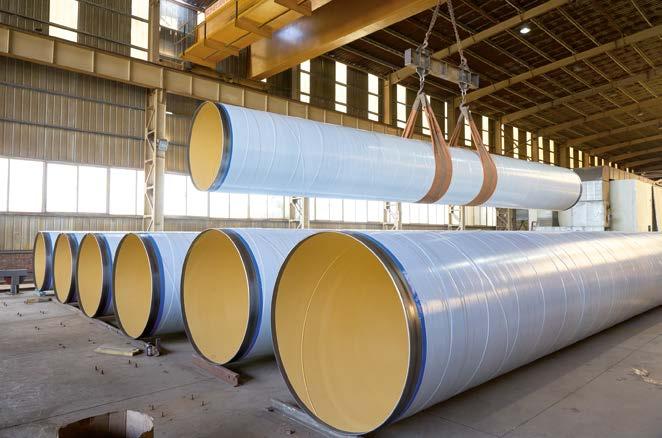
IBIX coatings meet the highest standards, offering cost-effective solutions to extend the lifespan of steel structures, pipelines, and machiner y Specif ic powder grades for Oil & Gas coating for 3LPE / 3LPP coating systems
Steelpaint coating delivers breakthrough in Wilhelmshaven dock gate renewal
Steelpaint has delivered a decisive breakthrough in the renewal of Wilhelmshaven’s Great Sea Lock (Germany), applying corrosion protection to some 26,000 m2 of steel on one of the world’s largest sluice gates.
At 60m long, 20m high, and with a depth of 10m, the 1700t gate provides access to Germany’s only deep-water port for naval vessels, commercial ships and energy carriers. The completion of the main coating work marks a significant step forward in a challenging project that started in 2018.
Steelpaint’s Stelpant coating system was selected after a twocomponent epoxy system from another supplier was found to be incompatible with an autumn/winter application, when freezing temperatures and near-saturated humidity can make epoxy coatings unusable.
Muehlhan Germany GmbH, which worked together with Hermann Maschinenbau GmbH in a working-group for port authority WNA Hannover & WSA Weser-Jade-Nordsee, opted for Steelpaint’s single-component polyurethane system Stelpant, which can cure at temperatures down to -5°C with a relative humidity up to 98%. Its use allowed the coating application work to continue through winter, ensuring the gate could be floated back into position and reinstalled for interim use.
The coating package consisted of a 75µm zinc-rich-primer of Stelpant-PU-Zinc followed by two 225µm coats of Stelpant-PUCombination 300. Together, the layers provide advanced corrosion protection against saltwater, abrasion and mechanical stress in one of Europe’s harshest marine environments.
The zinc primer provides cathodic protection and excellent adhesion, while the polyurethane intermediate and top coat delivers abrasion resistance, flexibility and durability even under aggressive marine exposure. The system is certified by the Federal Waterways Engineering and Research Institute in Karlsruhe for use in hydraulic steel structures and for environments from Im1 to Im3 under DIN EN ISO 12944-5.
“This was one of the largest and toughest projects we have been involved in the last few years, but it showed exactly what our technology can do,” said Fynn Baumfalk, Key Account Manager at Steelpaint. “The schedule slipped again and again and even now some areas remain unfinished, yet our coatings went on when and where they were needed and performed exactly as intended.”
Our market presence in Wilhelmshaven is growing more and more. First the Jade-Weser-Port, now the gate refurbishment and currently in progress is the refurbishment of sluice “Hooksiel”. The main corrosion protection on the refurbished gate is complete, though minor rework is required and some hot work also needs to be redone before recoats.
Baumfalk confirmed that the Stelpant coating system will also be used in these areas, with full commissioning of the gate expected in 2026.
The Wilhelmshaven Sea Lock sits at the mouth of the Jade, where the river meets the North Sea. Its location exposes it to salt corrosion, tidal erosion and abrasive silt, demanding the highest levels of protection.
The lock regulates water levels in Wilhelmshaven’s inner harbour, strengthens flood defences and provides safe access for both naval and merchant fleets. The port handles a major share of Germany’s crude oil, coal and LNG imports, while JadeWeserPort is the country’s only deep-water container terminal and the German Navy’s principal North Sea base. It has a natural depth of about 18m and can accommodate ships with an LOA of up to 430m and a 16.5 m draught.
The success of the Stelpant coating could see Steelpaint selected for further phases of JadeWeserPort dock’s wider renewal. Three entirely new dock gates are being discussed for commissioning towards the end of the decade. A feasibility study updated in 2019 confirmed the economic viability of a second container terminal 2km north of the existing one.
www.steelpaint.de/en/
Hempel appoints Malgorzata Kolton as new Executive Vice President & Head of Marine
Hempel A/S announced the appointment of Malgorzata (Gosha) Kolton as Executive Vice President & Head of Marine, effective 1 January 2026. Commenting on the appointment, Michael Hansen, Group President & CEO at Hempel says: “I am delighted to welcome Gosha to Hempel. Her international perspective, leadership experience and passion for innovation will be invaluable as we continue to strengthen our position in the marine coatings industry. Her commitment to building strong teams and customer-focused strategies will also help us deliver value for our stakeholders.”
Gosha brings extensive international experience in strategic and operational leadership across both developed and emerging markets. Her experience in leading complex transformations and delivering customer value aligns perfectly with Hempel’s strategic priorities and ambitions for the Marine segment “I am excited to join Hempel and the Marine team, and I look forward to working together to deliver outstanding value for Hempel’s customers and drive sustainable growth,” says Gosha Kolton.
A Polish national, Gosha joins Hempel from her role as EU Vice President of Packaging Adhesives, Coatings and Sealants at Henkel. In that position, she successfully steered one of the company’s largest regional businesses through volatile market conditions and transformations over the last five years, consistently delivering strong results across Europe.
Gosha takes over the role from Alexander Enström who has chosen to step down, following careful consideration and a desire to focus on more specialised responsibilities. He will assume the new role of Head of New Build in Marine from 1 January 2026. “The Executive Group Management, Board and I are deeply grateful for Alexander’s leadership and contributions as Executive Vice President & Head of Marine. We wish him every success in his new role as Head of New Build and look forward to his continued impact within the Marine team,” Michael Hansen concludes.
www.hempel.com
Why more research on corrosion protection leads to lower greenhouse gas emissions
EUROCORR 2025, the leading international conference for corrosion science and technology, took place from September 7-11 in Stavanger, Norway. Experts from around the world worked together to discover how to better protect components from corrosion. Effective protection extends the durability of components and significantly reduces the need for raw materials as well as emissions of greenhouse gases. “Protecting metals is an important topic in all areas of the industrial value chain. To minimise damage, for example from rust, we need interdisciplinary collaboration to research and develop new technologies and processes,” said Dr. Patrick Keil, corrosion protection expert at BASF Coatings. He is a senior executive of the organization that runs the EUROCORR conference series.
Corrosion has a significant negative economic impact worldwide. According to the IMPACT study1, published by the Association for Materials Protection and Performance (AMPP), the annual global costs of corrosion exceed 3 percent of global gross domestic product. Corrosion affects nearly all industrial sectors, such energy, chemicals and pharmaceuticals and their production facilities, as well as infrastructure such as bridges and pipelines, and transportation, including aviation, automotive, rail and shipping.
“The costs associated with corrosion are only one part of the problem. Corrosion is also a significant contributor to climate change,” Keil said.
This is illustrated by figures published in a 2022 study2: It is estimated that 15 to 33 percent of annual steel production is allocated to replacing corroded steel, accounting for 1.6 to 3.4 percent of global CO₂ emissions. “Researching innovative corrosion technologies and improving corrosion management is thus a key lever to increase sustainability,” said Keil.
Research with digital tools
At the headquarters of BASF Coatings in Münster, Germany, Keil and his team conduct research on corrosion protection using coatings and corrosion inhibitors. “These are chemical substances that increase the corrosion resistance of metals and alloys,” the researcher explained. One way they work is by forming a protective passivation layer which minimizes the contact with corrosive elements such as chloride ions, water and oxygen.
Keil also deploys digital tools in his research projects. Using machine learning and artificial intelligence, he analyses historical research data and chemical properties of molecules. These technologies aid in pattern recognition and predicting the most promising chemical compounds for corrosion inhibition. The effects of these compounds can also be simulated.
Onyax joins APCE: a technological contribution to the new challenges of cathodic protection
This year, Onyax, a telecommunications company designing and manufacturing low-power IoT dataloggers and AI platforms for industrial remote control and data monitoring, became a Local Member of APCE (Association for the Protection Against Electrolytic Corrosion). This membership reaffirms Onyax’s sustainable commitment to anti-corrosion solutions and allows the company to actively contribute to the technological innovation of traditional cathodic protection processes.
APCE is a cultural and scientific organization founded in 1981, dedicated to studying, promoting and disseminating best practices in cathodic protection.
This method is essential to preventing the corrosion of buried and submerged metal structures, such as oil pipelines, gas pipelines, tanks and maritime infrastructures, which are susceptible to deterioration caused by environmental and atmospheric agents. In this context, Onyax has been committed for years to researching and developing advanced IoT and AI technologies
that address the growing needs and challenges of an everevolving industry subject to continuous regulatory updates. With a particular focus on remote monitoring of cathodic protection for infrastructures, Onyax aims to optimise the management and security of distribution networks, offering operators and users low-impact environmental solutions, such as the BLACKBOX-CAT device. This innovative solution is designed to meet the latest requirements of the UNI 10950 standard revision, enabling the complete digitalization of control operations, including intelligent predictive activities. Thanks to the initiatives promoted by APCE, Onyax will benefit from a continuous growth path, allowing us to integrate into a cutting-edge ecosystem. Access to seminars, study days, events and support in applying cathodic protection guidelines1 will provide us with the opportunity to stay updated on the sector’s best practices.
In this way, Onyax’s approach to adopting new IoT and AI technologies in cathodic protection will help companies overcome the limitations of traditional systems and prevent corrosion-related damage, ensuring a safer and more sustainable future.
About Onyax
Onyax is an innovative SME composed of professionals with more than 25 years of experience in telecommunications and electronic engineering. The company specialises in hardware and software design, with a strong focus on sustainable technologies and on developing complete, flexible IoT solutions that meet the telemetry and remote monitoring needs of organisations seeking simplicity, security, and digitalisation in their industrial and urban control processes. The company integrates its devices through flexible and secure infrastructures designed to acquire, store, and process large amounts of data, making them available for management, predictive maintenance, optimisation, and process certification activities.
Onyax operates across multiple markets, including Industry 5.0, distribution and transport networks, smart cities and buildings, air and water quality monitoring, and smart agriculture.
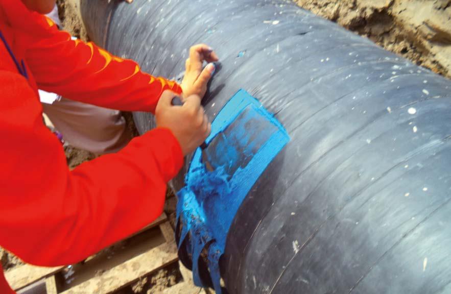
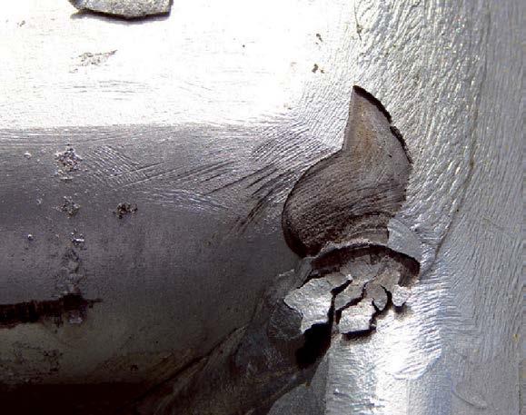
Industrial, petrochemical, offshore, and coastal facilities rely on closely spaced supports such as beams, saddles, and clamps, to carry the weight of above-ground piping. Those support points are where corrosion often starts. Coatings are scuffed, crevices hold thin films of salty water, and direct metal-tometal contact can set up galvanic cells. By the time the damage is obvious, you may already be looking at metal loss, leak risk, and costly repairs.
Common countermeasures, such as weld-on metallic wear pads, epoxied FRP wear pads, thermoplastic half-rounds, wraps, or simply more paint, can help, but they don’t always address the combination of sealing, electrical isolation, and coating protection needed at the interface, and many are slow or awkward to install in tight or offshore locations.
The SmartPad System was designed to prevent corrosion at the support locations by breaking the electrical path, sealing the pipe/ pad contact region against moisture, and shielding the coating— while also allowing the pad to be installed, opened for a visual check, and reinstalled, all in mere minutes.
Corrosion mechanisms at support interfaces
Crevice corrosion
A narrow, shielded gap under a support can trap a thin electrolyte film. Oxygen inside the gap is depleted while the surrounding surface remains aerated, creating an anode–cathode difference. Repeated wet–dry cycles concentrate chlorides and drop local pH, undermining the coating and driving localized corrosion.
The SmartPad effect: The closed-cell Hydroseal gasket is factorybonded to the saddle and compressed by band tension and pipe weight to make a continuous, conformal contact. That seal denies the tiny voids where films persist, while the FRP saddle spreads load so contact pressure stays more uniform through temperature fluctuations—both of which work against the creation of corrosion cells.
Galvanic corrosion
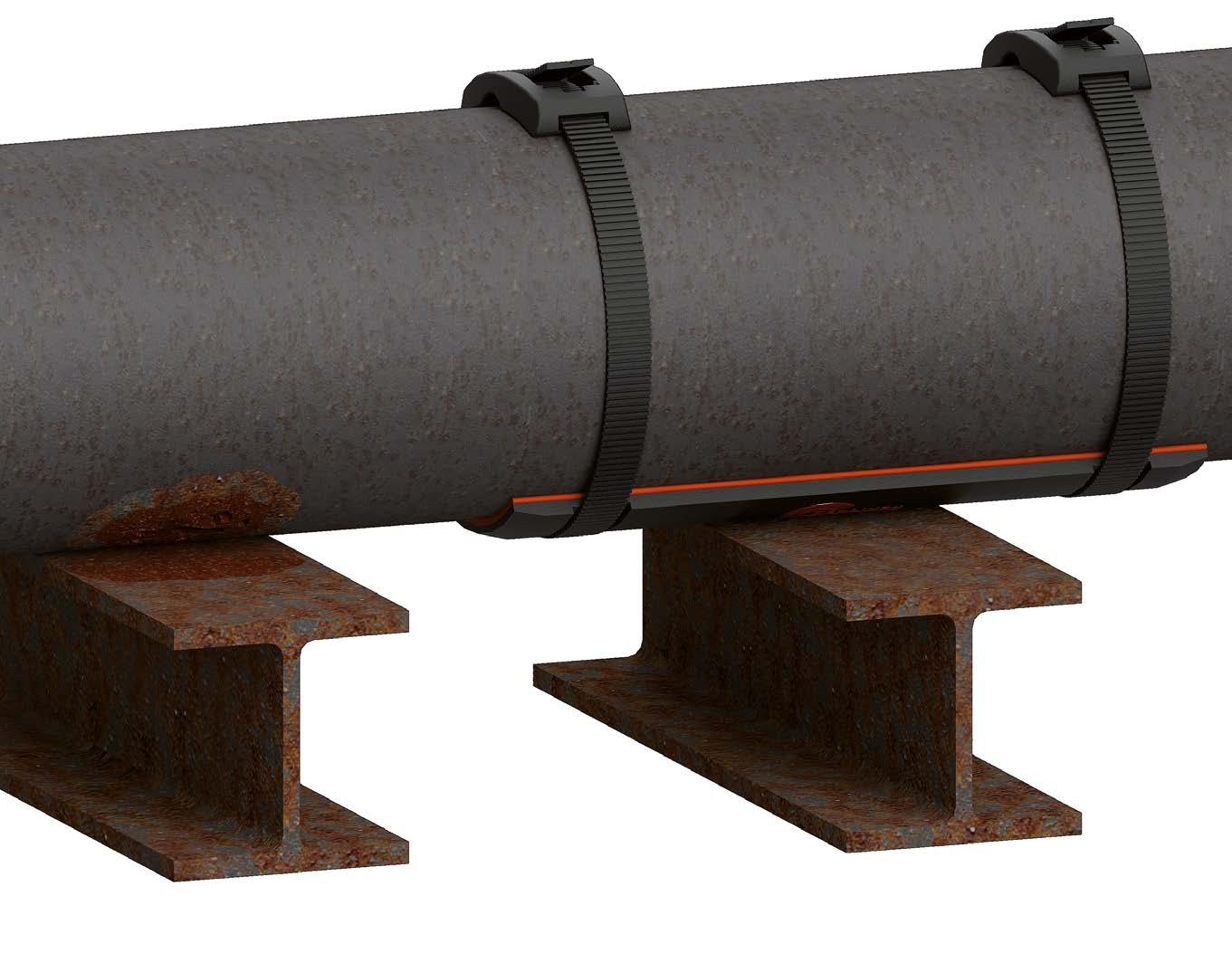
Pipe supports are frequent trouble spots for pipe external corrosion, often called CUPS (Corrosion Under Pipe Supports). Moisture that lingers at the contact surface, metal-to-metal contact, narrow crevices, and damaged coatings all play a part.
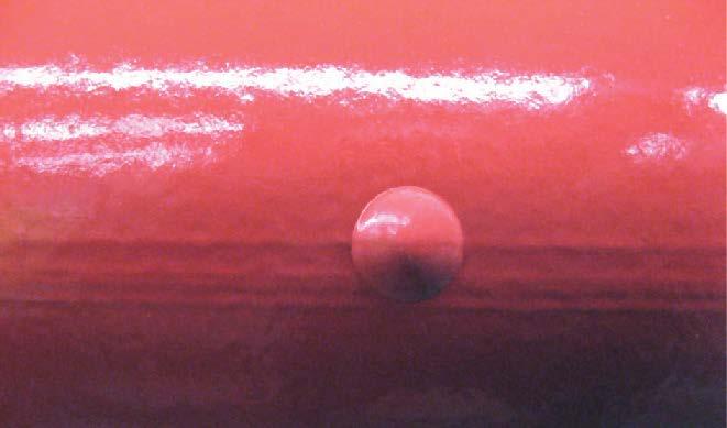
The SmartPad System (by RedLineIPS/Cogbill) is a non-metallic, FRP-based interface that tackles those root causes. Its components: an FRP saddle, a factory-bonded closed-cell Hydroseal gasket, composite polymer SmartBands with buckles, and a tensioning tool, all work together to electrically isolate the pipe from the support, seal out moisture at the contact surface, protect coatings, and make quick visual inspections practical. This article outlines the corrosion mechanisms involved, explains how the SmartPad is built and why it helps, and details its capabilities and advantages.
When the pipe and support are in electrical contact and share an electrolyte, the anodic surface corrodes. Small-anode/largecathode geometry at the support locations can intensify the effect. The SmartPad effect: The load path is fully dielectric--FRP saddle, Hydroseal gasket, and FRP bands/buckles--so metal-to-metal continuity at the interface is interrupted. At the same time, the sealed contact limits the shared electrolyte. Breaking the circuit and removing the film address both causes for galvanic corrosion.
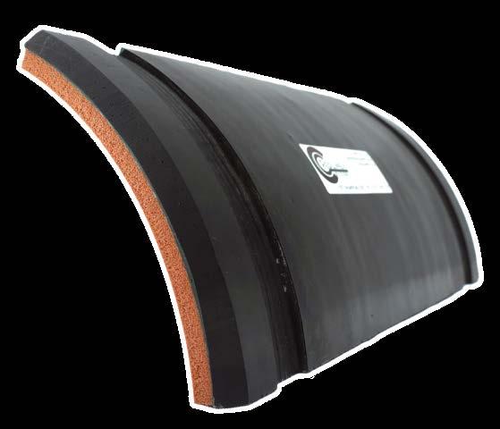
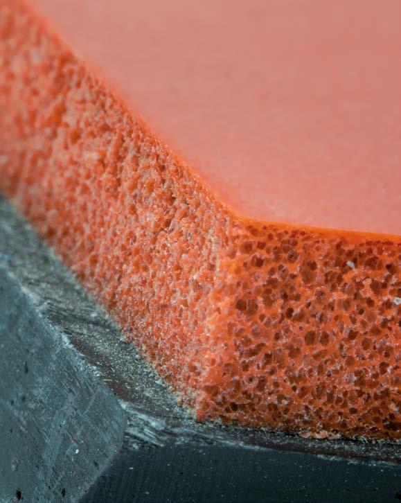
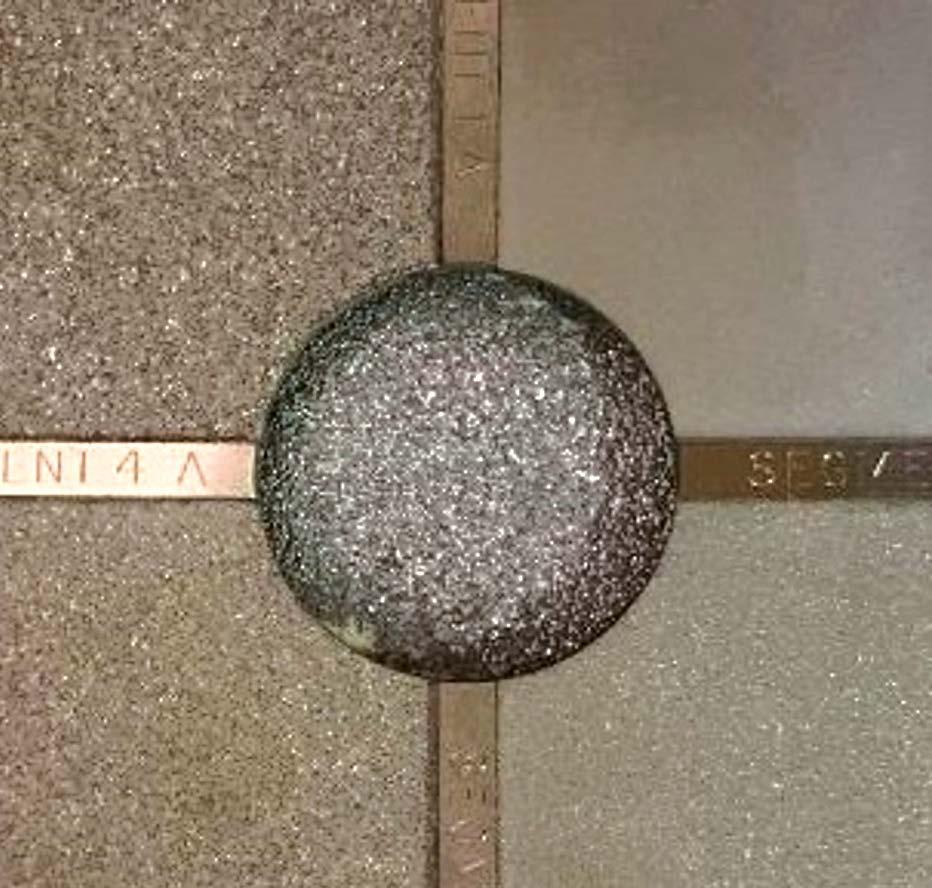
Photograph of the RedLineIPS SmartPad with bonded Hydroseal gasket, designed to eliminate corrosion under pipe supports.
Microbiologically Influenced Corrosion (MIC)
Intermittently wet crevices can host biofilms (e.g., sulfatereducing bacteria) that create sulfides, acidity, and local oxygen differentials, accelerating corrosion under deposits or within gaps. The SmartPad effect: The closed-cell Hydroseal gasket prevents water ingress between pipe and pad. This disrupts the conditions required for a corrosion cell under the pad. If needed, the banded pad can be opened quickly for a look and reinstated, supporting routine housekeeping and quick visual inspection.
Fretting-assisted corrosion
Minute relative movement at a hard contact, often from thermal cycling and support compliance, abrades paint coatings and passive films. Fresh steel then corrodes between slips, creating a wear–corrosion feedback loop concentrated at the support location. The SmartPad effect: The gasket cushions microirregularities and helps stabilize the pipe/pad contact, while the saddle’s broad bearing reduces local shear at the pipe wall. Thermal movement is managed at a controlled surface away from the coating, limiting the abrasion that seeds the loop.
Under-deposit / Capillary thin-film corrosion
Dirt, salts, or capillary-held moisture can behave like a hidden crevice beneath the footprint, keeping chloride-rich water in contact with steel components, which promotes corrosion. The SmartPad effect: A bonded, continuous gasket interface leaves no open seam for solids to wedge, and the closed-cell elastomer resists wicking. Moisture and debris stay on exposed, cleanable surfaces instead of migrating under the contact where you can’t see or reach them.
The SmartPad System
What it is and why it’s different SmartPad is a fully non-metallic support interface designed to stop corrosion where it most often starts - at the pipe/support interface. It installs without welding, drilling, or epoxy; crews wrap composite SmartBands, tension them with the SmartTool, and they’re done. In practice, installs are measured in minutes because there’s no surface prep, welding, drilling, or epoxy application and cure time.
Why it seals when epoxied pads don’t
A factory-bonded, closed-cell Hydroseal gasket is compressed between the FRP saddle and the pipe to create a NEMA 4–level watertight seal at the contact surface. That seal excludes the thin electrolyte films that drive CUPS. Because the gasket conforms like memory foam, it also seats cleanly on pipes with minor
SmartPad is a fully non-metallic support interface designed to stop corrosion where it most often starts - at the pipe/ support interface. It installs without welding, drilling, or epoxy; crews wrap composite SmartBands, tension them with the SmartTool, and they’re done.
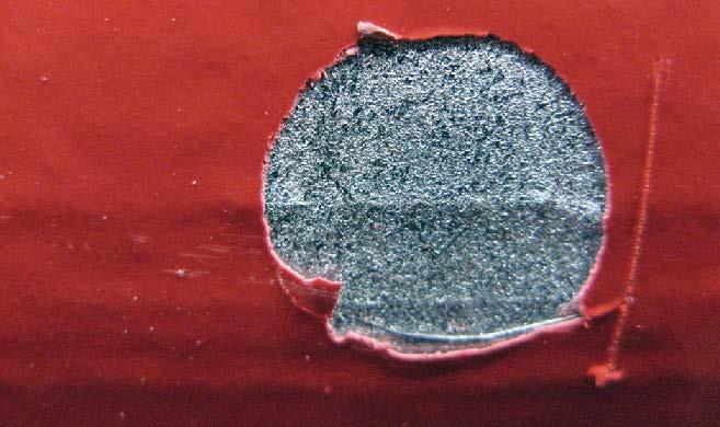
Close-up photograph of the Hydroseal gasket used in the RedLineIPS SmartPad System, showing its closed-cell elastomer structure designed to prevent moisture ingress.
unevenness or repairs from earlier corrosion work, conditions that often defeat epoxy-bonded FRP pads, which expect a uniform, bond-ready surface and long cure windows.
Open, look, and re-band
For pipe corrosion visual inspection, bands are cut, the pad is lifted for a quick visual, and new bands are tensioned back on. This reduces reliance on methods such as ultrasound, EMAT, or radiography for routine checks.
FRP SmartPad (the saddle)
What it is: a molded, saddle-shaped FRP wear pad matched to the outer diameter of standard pipe sizes, with recessed grooves that keep the bands low-profile and anchored. The composite body is dielectric, so it breaks the galvanic path between a steel pipe and a steel support while spreading bearing load so the paint isn’t crushed along a narrow line. Why it matters for corrosion: breaking metal-to-metal continuity removes one leg of a galvanic cell, and broad bearing helps preserve coatings that otherwise become moisture traps and crevice starters at the support locations.
Hydroseal gasket
What it is: a closed-cell elastomer sheet factory-bonded to the pipe side of the saddle. When the bands are tensioned and the line is set down, the gasket compresses into a continuous,
MECHANISM
Crevice / Differential Aeration
Galvanic
MIC Corrosion
Fretting-Assisted
Under-Deposit / Thin-Film
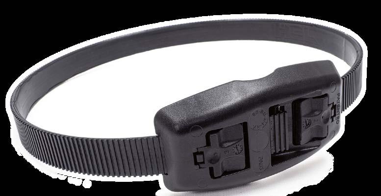
Photograph of a SmartBand used in the RedLineIPS SmartPad System. Made from continuous-strand fiber-reinforced polymer with a square-tooth locking mechanism, it provides long-term strength and corrosion resistance in harsh environments.
conformal contact. What it does against CUPS: compressed Hydroseal gasket creates a NEMA 4–level seal at the pipe/pad interface, excluding moisture that enables crevice/differential aeration, galvanic coupling, MIC niches, and under-deposit corrosion. Because it conforms, it seats over minor pits, filler, or profile left by earlier remediation, places where epoxied pads struggle to bond reliably.
MITIGATION PROCESS
Factory-bonded Hydroseal gasket compresses to a continuous, conformal contact, leaving virtually no voids for moisture ingress. The FRP saddle spreads load, keeping contact more uniform through temperature swings; the sealed interface blocks water droplets from invading the pipe/pad interface.
Fully non-metallic load path, FRP saddle, Hydroseal, non-metallic bands/buckles—interrupts metal-to-metal continuity. With electrical contact broken and moisture excluded, a galvanic cell is far less likely to form.
A dry, sealed, non-porous interface gives biofilms fewer places to establish. Rapid “lift-look-re-band” makes preventive cleaning and inspection practical.
The gasket cushions micro-irregularities and helps stabilize the contact; broad bearing reduces local shear at the pipe wall, limiting abrasion that exposes fresh steel.
A bonded, continuous gasket leaves no seam for solids to wedge or capillary films to linger; moisture and debris remain on exposed, cleanable surfaces.
ADVANCEMENTS
SmartBands, buckles & SmartTool
What they are: Long-strand composite polymer bands and matching FRP buckles with square-tooth engagement. Loop them through the pad’s grooves and tension with the SmartTool. The clamping path is fully non-metallic, so you don’t re-create a galvanic bridge while you’re trying to prevent corrosion. The SmartTool is available in manual, mechanical, and pneumatic versions. Why they matter for corrosion and uptime: The square-tooth profile is designed to hold tension over the service life of the pads (20-30 years or more, in typical environments), keeping the gasket properly compressed so the NEMA 4–level watertight seal at the pipe/pad interface persists. For corrosion inspections, cut the bands, lift and look, then re-band—no welding, drilling, or epoxy removal—which keeps visual inspections fast and realistic in the field, especially in confined spaces or at heights.
SmartPad System corrosion mitigation
Since corrosion mitigation at pipe support locations is the SmartPad System’s primary function, the table below offers a concise map from each corrosion driver to the specific SmartPad component that addresses it; use it as a quick, field-ready reference for design reviews, retrofit planning, and inspection briefings.
System capabilities & practical advantages
What it does at
the interface
Seals out the films that start corrosion. The closed-cell Hydroseal layer compresses against the pipe to form a tight, NEMA 4–level seal that blocks electrolyte films tied to crevice, under-deposit, and MIC-type corrosion.
Keeps the circuit from completing. The entire load path is nonmetallic, so there’s no metal-to-metal bridge at the support to
enable galvanic attack.
Protects the coating you already paid for. A contoured FRP saddle with broad bearing and smooth, radiused edges spreads load instead of pinching it along a knife-line, helping the coating survive at the support.
What it does for installation and access
No welding, drilling, or epoxy and cure time. Wrap the bands, tension with a handheld tool, and you’re done—hot work permits not required, no cure windows. Typical installs take minutes, not hours.
Works on imperfect pipe surfaces. If a line was blasted, filled, or spot-repaired after earlier corrosion, the closed-cell gasket conforms and seals; it doesn’t demand a perfectly smooth, bond-ready surface.
Made for real inspections. To check underneath, cut the bands, lift and look, then re-band. Because that takes minutes, routine visual inspections actually happen—before corrosion has time to hide and grow. This reduces the reliance on costly corrosion inspection methods such as EMAT, ultrasound, X-Ray, etc.
What it does for reliability
Holds preload. Composite polymer bands and matching squaretooth buckles are designed to maintain tension so the gasket stays compressed and the seal persists.
Stays non-conductive. Every path through the assembly is dielectric by design; you don’t short-circuit the isolation while securing the pad.
Handles the environment. The vinyl-ester FRP saddle and closed-cell elastomer are suited for outdoor service in wet, salty, and UV-exposed locations, with a broad temperature window typical of process facilities. The SmartPad System was designed for offshore and coastal plants and platforms.
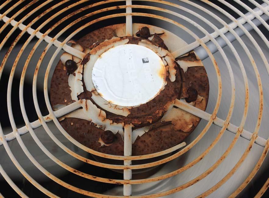
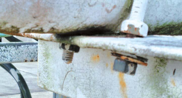
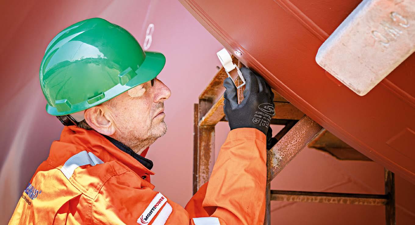
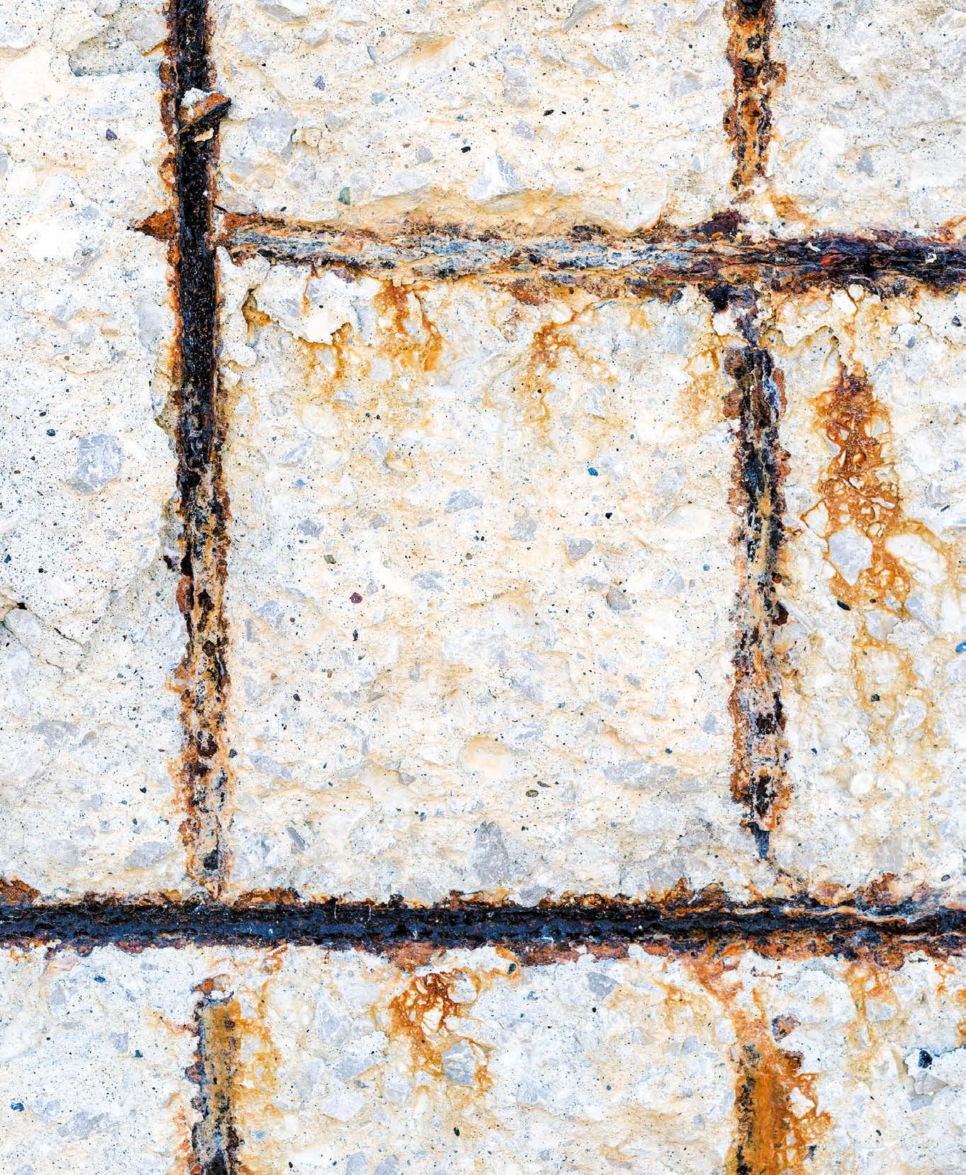
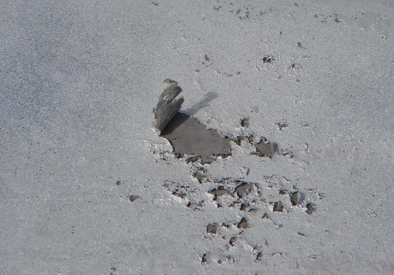
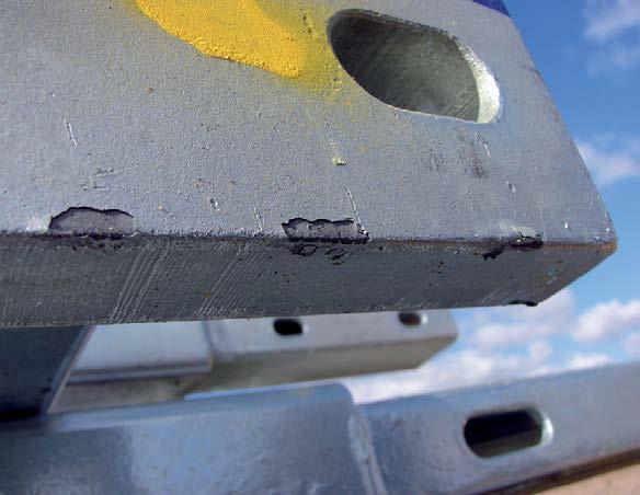
Example of CUPS (Corrosion Under Pipe Supports), where trapped moisture and crevice conditions have led to rust and coating breakdown.
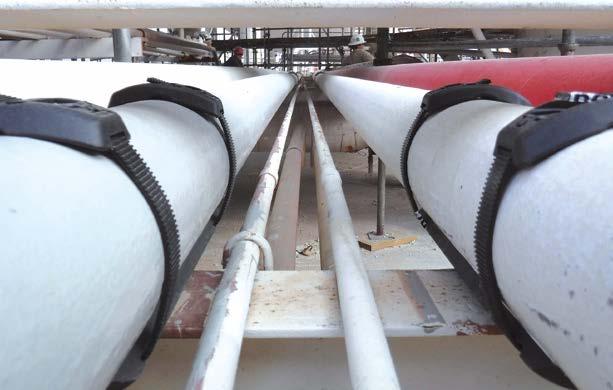
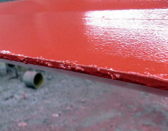
Field view of the SmartPad System on parallel process lines—FRP saddle with bonded closed-cell gasket secured by fiber-reinforced thermoplastic SmartBand straps.
What it does for schedules and costs
Fewer delays. No hot work or permits, no adhesive cure time, and no grinding off old epoxies, all mean fewer reasons to push a small support job into the next outage.
Less specialized gear. A hand tool sets tension; crews don’t need welding rigs or costly skilled welders, curing tents, or surface-prep stations at every support.
Re-use where it makes sense. Saddles and buckles are durable; bands are low-cost consumables. Keeping spare band stock on hand makes “lift-look-re-band” a quick, routine task.
Conclusion
Corrosion at supports starts where the pipe meets the steel.
SmartPad tackles that contact directly: an all-composite load path breaks electrical continuity, a compressed closed-cell interface keeps moisture out, and the contoured FRP saddle protects the coating. It installs in minutes—no welding, drilling, or epoxy—and seats reliably even on slightly uneven or previously repaired pipe. Just as important, it makes inspection practical: cut the bands, liftlook-re-band, and move on.
On turnarounds or tight offshore decks, those practicalities keep the interface clean, dry, and isolated. The result is a straightforward, scalable way to reduce CUPS risk across large piping systems. ‹
Corrosion at supports starts where the pipe meets the steel. SmartPad tackles that contact directly: an all-composite load path breaks electrical continuity, a compressed closed-cell interface keeps moisture out, and the contoured FRP saddle protects the coating.
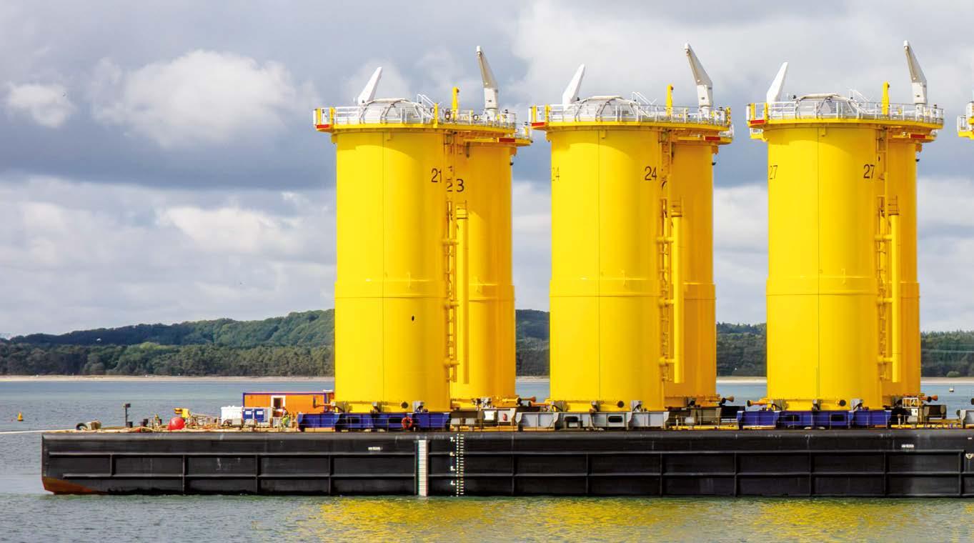
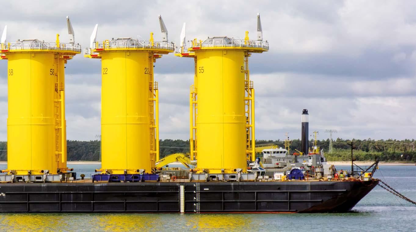
OFFSHORE WIND SECTOR MUST UNITE TO FUTURE-PROOF RENEWABLE ENERGY INVESTMENT
Now is the time for unified, performance-based corrosion protection standards in offshore wind, says Sherwin-Williams.
ROAD TO 2050
Sherwin-Williams, a world leader in paints and coatings, is calling for collective action to develop a tailored, international corrosion protection standard for offshore wind installations. Without it, the company says, innovation will continue to be stifled by outdated guidelines and inconsistent practices.
Emerging efforts to develop a dedicated offshore wind corrosion protection standard, such as ISO/AWI 25249, offer a vital opportunity to secure the longterm reliability, cost-effectiveness, and sustainability of the sector. It is an opportunity that cannot, and should not, be missed.
How current standards fall short
From immersion in saltwater, strong currents, wave impacts, and oxygenrich splash zones, offshore wind structures endure harsh and unforgiving conditions. But with no globally recognised standard guiding corrosion protection, wind turbine foundations are too often left vulnerable to premature degradation.
Historically, the industry has borrowed corrosion protection practices from the oil and gas sector. Yet these practices are ill-suited to the task. While oil & gas EP platforms are regularly maintained, offshore wind facilities are unmanned, exposed to far more dynamic marine conditions, and expected to operate with minimal maintenance for 30 years or more.
Early attempts to apply standards such as ISO 12944-9 (previously ISO 20340), and NORSOK M-501 provided a helpful starting point. But they were only ever designed for 15-year durability. As such, we are seeing coatings fail early, especially in high-risk areas such as the splash zone, resulting in the need for expensive, complex repairs. Germany’s VGBE-S-021-03 standard (now on its 4th edition, issued 2023), introduced more performance-based testing, tailored to offshore wind. However, its adoption has been largely regional, and some testing protocols are not compatible with modern, solvent-free coating systems.
Meanwhile, newer tools like ISO 24656:2022 that focus on cathodic protection design and classify coatings based on perceived field performance, were never intended as specification standards. As a result, misinterpretations have led some developers to favour outdated compositions over innovative technologies that could offer better long-term performance.
The Path Forward: innovation through standardisation
The industry needs a smarter, unified framework: a performancebased, international standard specifically designed for offshore wind. Such a standard should:
Set clear durability benchmarks of 25 to 35+ years, to align with the realities of offshore wind operations;
Remove prescriptive compositional requirements in favour of real-world performance testing;
Incorporate practical testing protocols that reflect fabrication, application, and inspection conditions, rather than just laboratory simulations;
Promote sustainability, favouring low-carbon, solvent-free coatings that reduce reliance on cathodic protection and high-alloy steel;
Support global harmonisation, simplifying procurement, improving quality assurance, and reducing cost and time delays for fabricators.
ISO/AWI 25249 gives the industry an opportunity to unite around these principles.
Joao Azevedo, Energy Segment Director – EMEAI, SherwinWilliams Protective and Marine Coatings, said: “The success of offshore wind as a long-term, low-carbon energy source depends on reliable, sustainable, and cost-effective corrosion protection. Without standardised guidelines tailored to offshore wind’s specific challenges, the sector risks undermining investor confidence, compromising safety, and inflating operational costs.
“We call on developers, fabricators, coating manufacturers, standards organisations, and policymakers to come together to drive the creation of a global corrosion protection standard that puts performance, practicality, and sustainability at its core. The future of offshore wind isn’t just about what we build. It is about how we protect it”, he continued. ‹
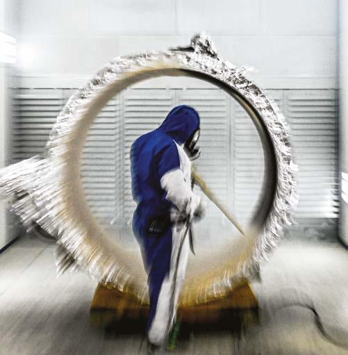
In
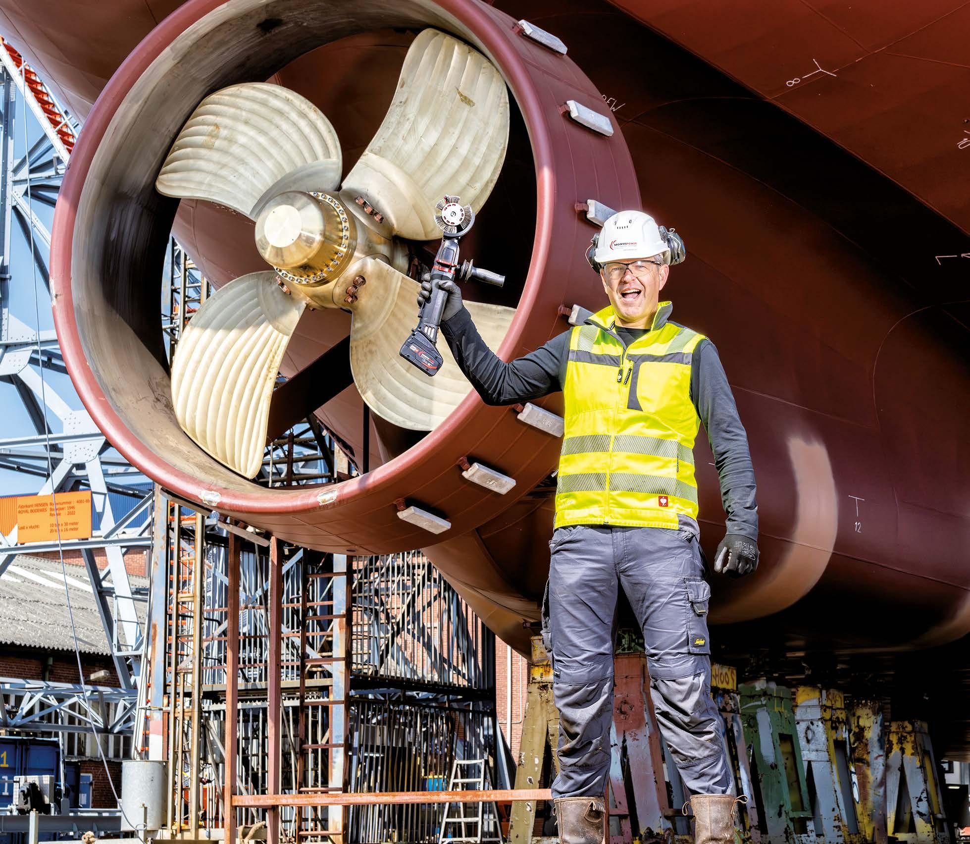
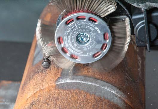
Monti Group has spent decades pioneering a surface preparation method that is comparable to conventional ‘sand’ blasting: the Bristle Blaster®. Today, it is the only power tool-based technology in the world that achieves visual cleanliness and an uniform anchor profile comparable to loose abrasive blasting, without the operational complexity and environmental challenges that come with loose media such as grit.
Why surface preparation matters so much
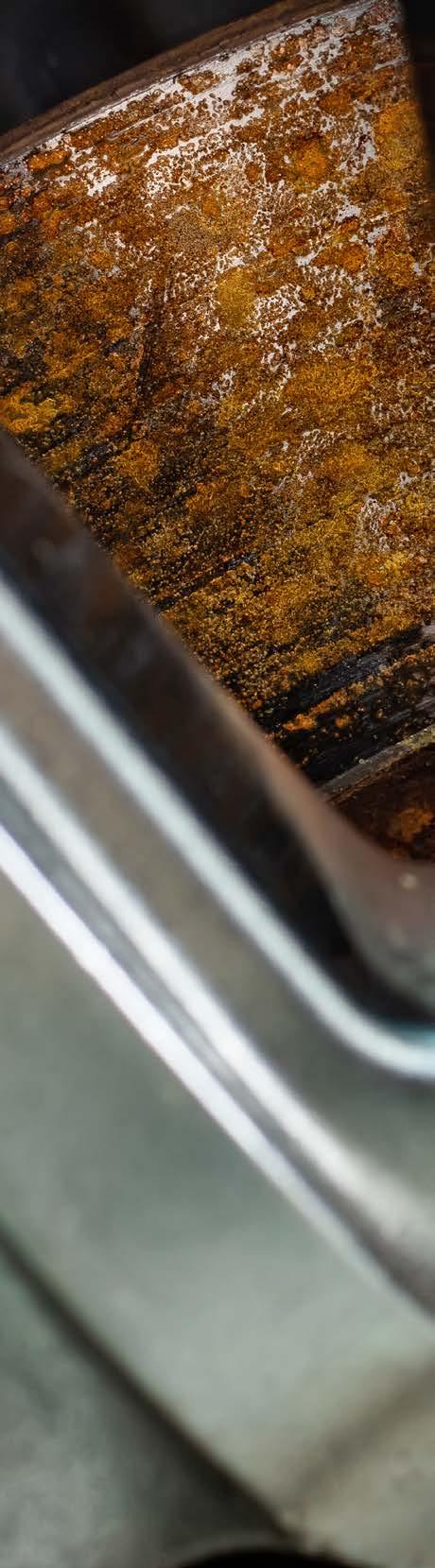
Before diving into what sets the Bristle Blaster® apart, it is worth re-emphasizing a universal truth: coating performance is only as good as the substrate preparation. Even the highest-grade epoxy, polyurethane, or anti-fouling system will fail prematurely if applied over poorly prepared steel. This is particularly true in coastal outdoor areas where steel is constantly under attack - from saltwater, UV radiation, cargo residues, and changing humidity. Traditionally, grit blasting has been seen as the gold standard for removing corrosion and old coatings. But is it always the best - or even the most practical - option? Monti Power believes the answer is often “no.” The following explains why.
The problem with traditional blasting methods
Loose abrasive media blasting requires infrastructure: compressors, hoses, containment systems, recovery equipment, and highly trained operators. On a dry dock, that might be manageable. But when vessel is at anchor, on a voyage, or docked in a port with environmental restrictions, grit blasting becomes a logistical headache - and sometimes entirely prohibited. Moreover, grit blasting generates enormous volumes of wastespent abrasive, old coatings, rust, and often contaminated dust. This not only poses environmental challenges but also raises disposal costs and can delay maintenance.
the world of asset integrity and steel maintenance, time is money - and surface preparation is everything. Whether you're a superintendent overseeing dry-dock schedules, a ship captain responsible for operational uptime, a corrosion engineer aiming for maximum longevity, or a maintenance engineer tasked with rust removal, you understand how critical it is to prepare steel surfaces the right way.
The patented Bristle Blaster® is the only power tool in the world that is comparable to ISO 8501-1 Sa2½ to Sa3 visual cleanliness and generates a surface roughness/profile from 50 μm, ideal and crucial for bonding a coating and adhesives.
Then there is the issue of surface accessibility. Tight corners, vertical bulkheads, flange edges, ballast tanks, or container undersides are not always accessible with large blasting equipment. Crews need a more mobile, controllable, and precise solution.
The Bristle Blaster® advantage: blasting without grit
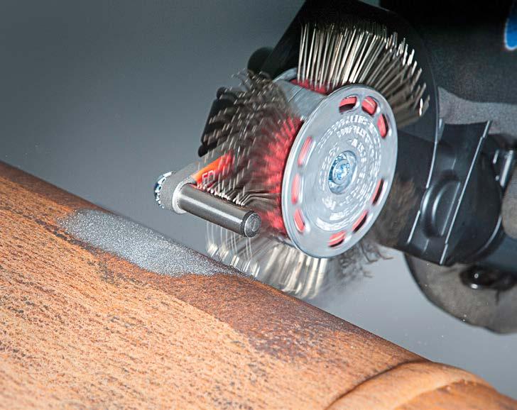
The patented Bristle Blaster® bridges the performance of grit blasting with the practicality of hand tools. It is the only power tool in the world that is comparable to ISO 8501-1 Sa 2½ to Sa 3 visual cleanliness and generates a surface roughness/profile from 50 µm - ideal and crucial for bonding a coating and adhesives. Here is how it works: the tool features specially hardened bristle tips that rotate at high speed and are dynamically tuned to strike the steel surface at an optimal angle. The result is simultaneous corrosion removal and micro-anchoring, all in one step - without the need for blasting media or secondary clean-up.
The result of using the Bristle Blaster®is simultaneous corrosion removal and micro-anchoring, all in a single operation - without the need for blasting media or secondary clean-up.
Let is break down the real-world benefits:
1. Mobility and accessibility
From ballast tanks to deck edges to inside of containers, the Bristle Blaster® allows crew or maintenance contractor to access confined or vertical spaces where blasting rigs simply cannot reach. Whether you are working at sea, on deck, or in port, Monti Group’s compact tools operate reliably from a power outlet or pneumatic source - no compressors or containment tents needed.
2. Environmental stewardship
Whether it is captains or superintendents, everyone knows how strict port regulations have become. Many jurisdictions now restrict or ban abrasive blasting unless fully enclosed systems are used. The Bristle Blaster® produces no abrasive waste, no airborne media, and minimal dust, making it ideal for environmentally sensitive locations or in-transit maintenance, and the bristles remain clean.
Monti Group’s compact tools operate reliably from a power outlet or pneumatic source, at sea, on deck, or in port – no compressors or containment tents required.
3. Lower cost and faster deployment
Grit blasting setups can take hours to assemble and require multiple operators and cleanup crews. In contrast, the Bristle Blaster® is plug-and-play, allowing rapid mobilization and deployment - even during a port call or cargo turnaround. This drastically reduces labour, consumables, and downtime costs.
4. Verified coating compatibility
Surface profile has been validated by leading coating manufacturers across the marine and offshore sector. Monti Group routinely tests Bristle Blaster® surfaces with coating partners and independent laboratories to verify pull-off adhesion, edge retention, and long-term corrosion resistance. In some cases, coatings have performed better on bristle blasted surfaces due to cleaner, sharper anchor patterns with fewer contaminants and therefore immediate flash-rust risk.
5. Safety and control
Grit blasting is inherently hazardous - flying media, pressurized hoses, visibility issues, and confined space risks. The Bristle Blaster® offers a controlled, operator-friendly alternative that significantly reduces noise, dust, and risk of injury. It is also safer for surrounding crew and equipment, especially on active vessels.
Use cases from the field
Bristle Blaster® has been used across all classes of vessels: bulkers, tankers, offshore platforms, ferries, and container ships. One major liner operator recently used it during a mid-voyage coating spot repair on deck fittings - saving a planned dry-dock intervention.
In another case, a container leasing company deployed Bristle Blasters across its global refurbishment hubs, drastically cutting abrasive consumption and enabling local teams to work without permits or special waste disposal.
Closing thoughts: future-proofing a maintenance strategy
The maritime industry is evolving under increasing pressure: environmental regulations, tighter schedules, and aging fleets demand agile, efficient, and sustainable maintenance tools. The Bristle Blaster® is not here to replace grit blasting in every case, but to give a valuable and certified alternative - one that is cleaner, more precise, and better suited to modern marine operations.
“In Monti Group we are committed to solving real-world maintenance challenges for real-world people. We work with your coating suppliers, your technical managers, your shipyards, and your classification bodies to ensure every application of our technology meets the highest performance standards. If you have not experienced the Bristle Blaster® yet, we encourage you to try it. Because in the end, what matters is not just cleaning steel – it is preserving value, reducing downtime, and extending asset life. That is what we are here for,” concludes the company. ‹
The Bristle Blaster® is not here to replace grit blasting in every case, but to give a valuable and certified alternative - one that is cleaner, more precise, and better suited to modern marine operations.
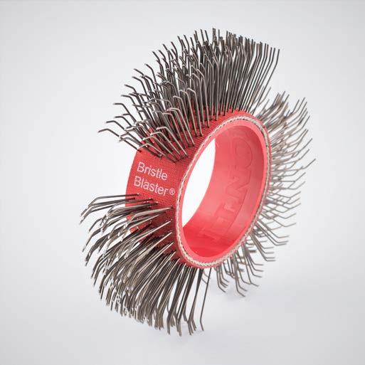
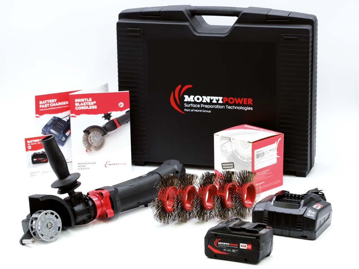
Bristle Blaster® Set.
Prevention of the stiction phenomenon of automotive braking systems
M. Motta*, L. Fedrizzi1, A. Sin2,3 and F. Andreatta1
1 University of Udine, Polytechnic department of engineering and architecture, Via del Cotonificio 108, 33100 Udine, Italy
3 Joint Lab ITT- UniTO, via Quarello 15, 101135 Torino (TO), Italy
*Corresponding author: michele.motta@uniud.it
The automotive braking system of a vehicle can be exposed in service to extremely variable and potentially aggressive conditions, including rain, snow, SOx and NOx-rich atmospheres, and chloride-containing environments. As a result, the different components of the braking system might undergo corrosion during service.
This can result in several issues ranging from aesthetic problems to critical aspects impairing its reliability. One common corrosion related issue is the static-friction (stiction) phenomenon, which is the target of this article. A new testing procedure for the study of stiction propensity of friction materials has been developed. This work describes its application in the study of friction materials containing corrosion inhibitors in order to prevent stiction susceptibility.
The stiction phenomenon
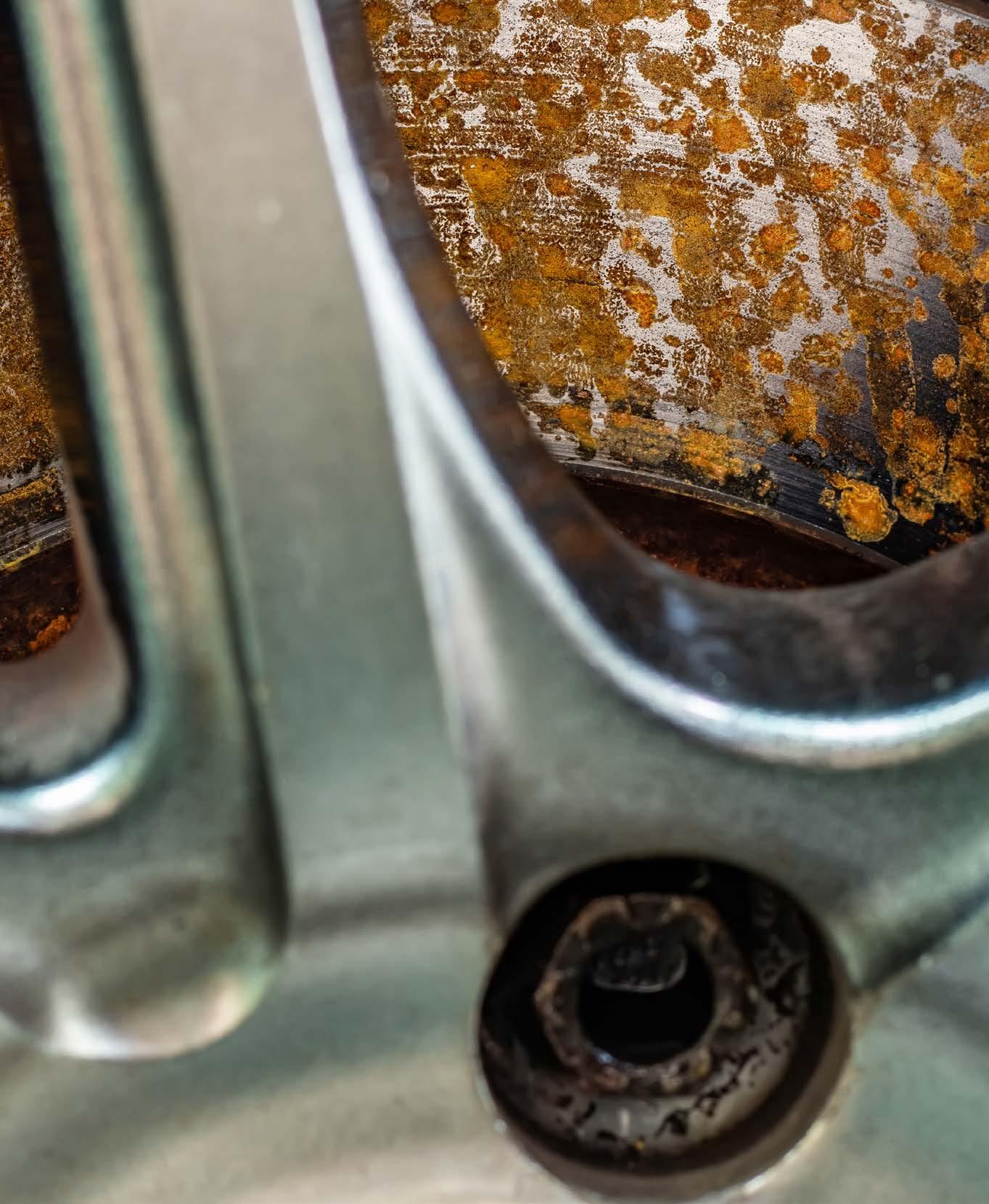
The stiction phenomenon is the adhesion between the friction material and the grey cast iron rotor caused by the penetration of corrosion products in the brake pad. It occurs when a static clamping force between the rotor and the friction material is applied for prolonged stationary periods of the vehicle in a corrosive atmosphere [1–3]. This typically occurs when the parking brake is activated. Stiction can be critical, especially during the vehicle startup phase. In this situation, if the adhesive force (stiction force) is sufficiently elevated, the release of the parking brake can damage the friction material and, in the worst-case scenario, it can preclude the use of the vehicle. The stiction phenomenon is extremely complex to study since it can be affected by the environmental conditions but also by the
grey cast iron disc and the formulation of the friction material [4–6]. In particular, the pad formulation is very complex and often consists of several different constituents [3,7,8], including materials capable of exerting a galvanic action, such as copper, graphite, and zinc [3,5,9–11]. Time-consuming vehicle tests and laboratory measurements based on the ISO 6315 standard are the most employed procedures to characterize the stiction propensity of a friction material [12]. These procedures typically include a conditioning phase, followed by the clamping between the rotor and the pad and a specific treatment in the humidity chamber [4,13]. In order to reduce the time necessary to study the stiction behaviour of newly formulated friction materials, ITT Italia, in collaboration with the University of Udine, developed a new electrochemical test that can be used to develop new stiction- and corrosion-resistant brake pads [14].
Stiction test - a new experimental technique
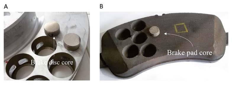
The stiction test developed by our research team employs cores of friction materials and brake discs as shown in Figure 1 to evaluate the stiction behaviour of a friction material on a smaller scale as compared to conventional methods. This enables to perform several tests using a single brake pad at laboratory scale with a test duration that is considerably lower than vehicle tests typically employed in the field.
Friction material cores with 1 cm diameter are extracted from a brake pad and levelled to a height of 0.5 cm. Similarly, cores with 2 cm diameter are extracted from the grey cast iron disc. An electrical contact with a copper conductive wire is made on the back of the disc cores, which are embedded in epoxy resin. The surface of the disc and the friction material samples are ground up to 220 grit to simulate the typical roughness
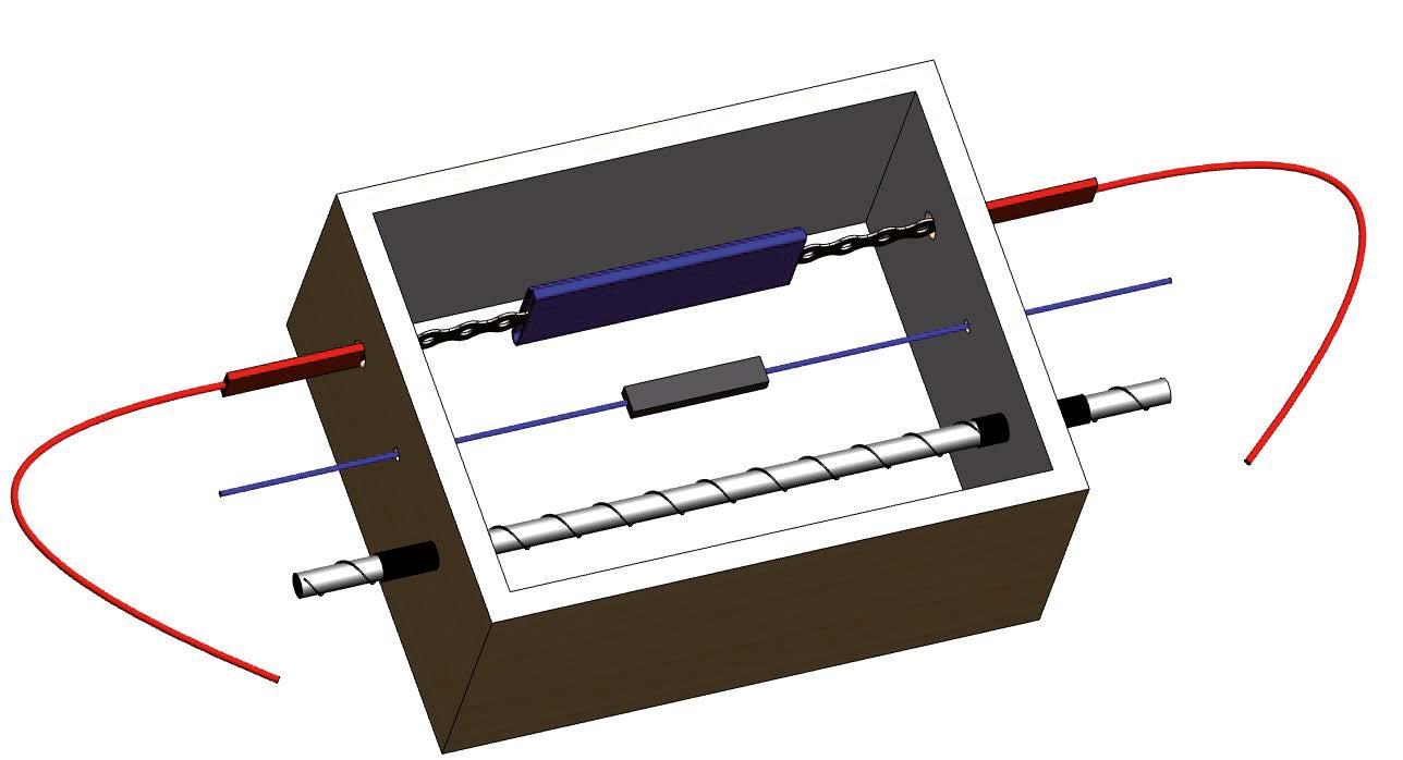
Figure 1 - Brake disc (A) and brake friction material cores (B) used to perform the stiction tests.
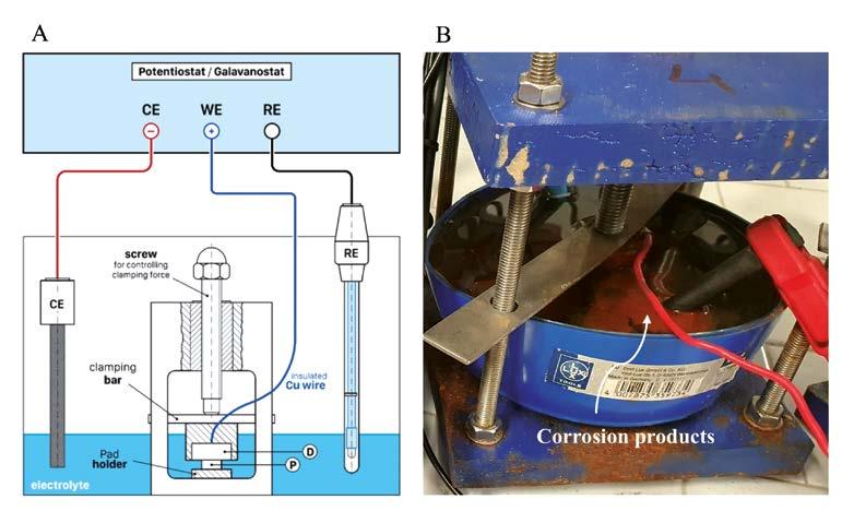
Figure 2 - Schematic representation of the cell used for the coupling of the disc (D) and the friction material (P) samples (A), Corrosion products due to grey cast dissolution after the stiction test (B).
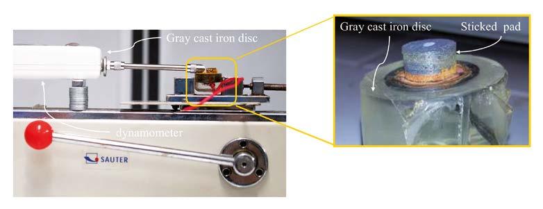
Figure 3 - Bench dynamometer for the measurement of the stiction.
of brake discs and friction materials in service. The brake assembly can then be simulated by coupling the cores of the disc and friction material with a clamping force simulating the parking brake. This can be accomplished using the electrochemical cell visible in Figure 2A With reference to Figure 2, the friction material core (P), is placed in a specific holder. The grey cast iron disc core (D), embedded in epoxy resin and with the electrical connection described above, is placed on top of the friction material core with the metallic surface engaged on the surface of the friction material. The screw visible in Figure 2A is employed to apply a clamping force simulating the brake calliper of a real vehicle engaged on the disc when the parking brake is activated. To electrochemically induce the stiction phenomenon with a threeelectrode configuration, the disc-friction material assembly (working electrode) is immersed in 0.1 M NaCl solution. A graphite bar is used as counter electrode (CE) and an Ag/AgCl (3 M KCl) electrode serves as a reference electrode (RE). An electrochemical workstation is employed to induce the stiction phenomenon by means of an optimized electrochemical procedure [14]. This test procedure can induce the stiction phenomenon in the brake disc/pad assembly in approximatively 24h enabling a fast assessment of the stiction behaviour. At the end of the stiction test described above, the disc is usually strongly adhering to the friction material. The stiction force, which is the tangential force necessary to detach the pad sample from the disc sample, can be measured with a bench dynamometer, as shown in Figure 3. The stiction force is a quantitative parameter that is well correlated with the stiction propensity of the friction material, as demonstrated by comparing vehicle tests with the testing procedure described above.
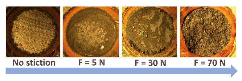
Figure 4 - The relation between the measured stiction force and the appearance of the surface of the disc after detachment of the pad sample in the stiction test.
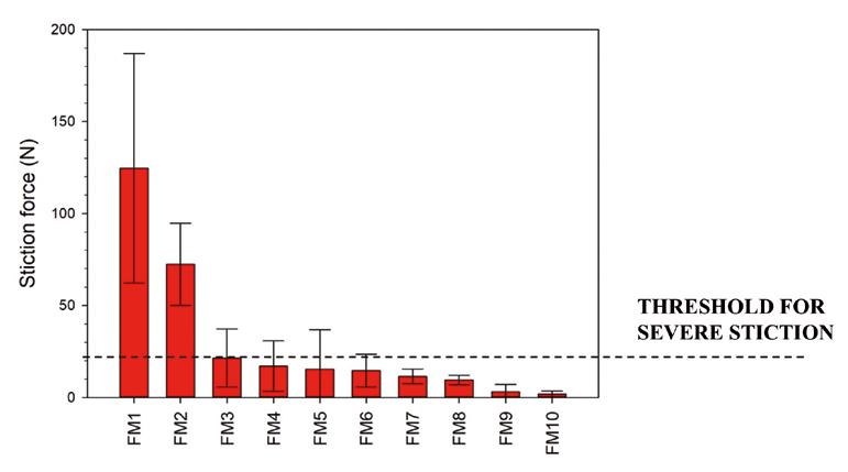
Figure 5 - Stiction force of friction materials with different composition.
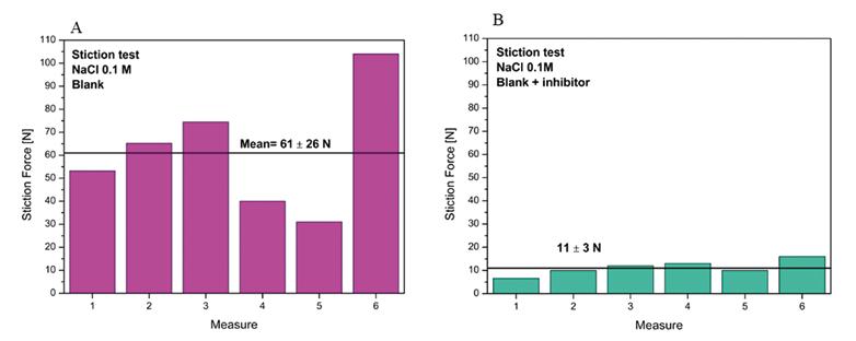
Figure 6 - Stiction force for stiction tests performed in a 0.1 M NaCl solution without (A) and with inhibitor (B) in the friction material.
Stiction behaviour of friction materials
As shown in Figure 4, the measurement of the stiction force and the evaluation of the surface of the disc sample after detachment form the pad sample, enable to evaluate the stiction susceptibility of the friction material. Increasingly high stiction forces are typically associated to a higher stiction propensity, which in the worst cases is associated to severe damage of the friction material (Fig. 4). Indeed, as visible in Figure 4, the disc surface does not show evident corrosion or adhesion of friction material when stiction is not observed. In contrast, a high stiction force is associated to severe corrosion and marked adhesion of friction material on the disc sample.
The stiction test can be employed for the evaluation of different friction materials, as shown in Figure 5, which gives the stiction force measured for 10 different friction materials. Vehicle tests indicated that a stiction force of 20 N can be assumed as a threshold for severe stiction. Therefore, the test protocol described above enables a fast screening of the stiction behaviour of different friction materials limiting the time-consuming vehicle tests only to friction materials that display low stiction force in laboratory tests.
Control of stiction phenomena in automotive braking systems
The use of corrosion inhibitors is one of the approaches that can be followed to limit stiction susceptibility of friction materials [3]. Our research group is currently focusing on the use of environmentally
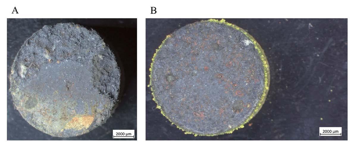
friendly corrosion inhibitors directly introduced inside the friction material. An example is oxalate-based inhibitors, which can be introduced as additives in the formulation of the friction material. Figure 6A shows the stiction force measured for 6 samples of a friction material that displays high stiction susceptibility in vehicle tests. The stiction force measured following the electrochemical procedure described above is generally high for this material and well above the threshold for high stiction propensity. This is well in line with the vehicle tests performed with the same friction material (not reported here). Figure 6B reports the stiction force for the same friction material containing an oxalate-based inhibitor. In this case, the introduction of the inhibitor in the formulation led to a reduction of the average stiction force from 61 N to 11 N, while maintaining the tribological properties of the pad almost unchanged relative to the friction material without inhibitor. This is also confirmed by the morphology of the pad samples of the friction material without inhibitor (Figure 7A) and with the inhibitor (Figure 7B) after detachment form the disc. Indeed, Figure7A clearly shows severe damage for the friction material without inhibitor, possibly impairing the reliability of the vehicle during braking. In contrast, the friction material containing the inhibitor displays no relevant damage although some corrosion products are visible on the pad (Figure 7B). In this case, the oxalate-based inhibitor can effectively limit corrosion processes at the rotor/pad interface leading to a reduction of the stiction susceptibility. This is a clear indication that the inhibitor is potentially applicable in the design of new friction materials.
Figure 7 - Stereomicroscope image of the friction material without (A) and with inhibitor (B) after the stiction test.
Conclusions
The stiction test is a newly developed time-saving procedure that can be used not only to characterize the stiction propensity of existing friction materials but also to develop new corrosion- and stiction-resistant brake pads. In this context, protecting grey cast iron brake discs from corrosion-related issues, such as stiction, has become a critical challenge to address in order to reduce heavy metal emissions from braking systems. This is particularly important in electric vehicles, where regenerative braking significantly reduces the use of conventional braking, meaning that the traditional system is expected to last for almost the entire lifetime of the vehicle. Given the inherent challenges of working with complex multi-materials such as brake pads, the stiction test has proven to be one of the most effective methods for evaluating new friction materials with corrosion inhibitors designed to provide long-lasting protection against stiction and related corrosion phenomena. ‹
The stiction test is a newly developed time-saving procedure that can be used not only to characterize the stiction propensity of existing friction materials but also to develop new corrosion- and stiction-resistant brake pads.
References
[1] Gweon J, Shin S, Jang H, Lee W, Kim D, Lee K. The Factors Governing Corrosion Stiction of Brake Friction Materials to a Gray Cast Iron Disc. SAE Technical Papers, vol. 2018- October, SAE International; 2018. https://doi.org/10.4271/2018-01-1899.
[2] Gweon J, Park J, Lee WK, Kim DY, Jang H. Root cause study of corrosion stiction by brake pads on the grey iron disc. Eng Fail Anal 2021;128. https://doi.org/10.1016/j. engfailanal.2021.105583.
[3] Motta M, Fedrizzi L, Andreatta F. Corrosion Stiction in Automotive Braking Systems. Materials 2023;16. https://doi.org/10.3390/ma16103710.
[4] Merlo F, Passarelli U, Pellerej D, B+uonfico P. Effect of gray cast-iron microstructure and brake pad formula on wear behavior and corrosion sticking influenced by thermal preconditioning: The copper role. SAE Technical Papers, vol. 7, SAE International; 2012. https://doi.org/10.4271/2012-01-1836.
[5] Passarelli UP, Merlo F, Pellerej D, Buonfico P. Influence of brake pad porosity and hydrophilicity on stiction by corrosion of friction material against gray cast iron rotor. SAE Technical Papers, vol. 7, SAE International; 2012. https://doi.org/10.4271/2012-01-1803.
[6] Tigane R, Bauwens D, Hude O, Joiret S, Keddam M, Turmine M, et al. On the local corrosion in a thin layer of electrolyte separating two materials: specific aspects and their contribution to pad-to-disk stiction in automobile brake system. Journal of Solid State Electrochemistry 2021;25:895–904. https://doi.org/10.1007/s10008-02004867-w/Published.
[7] Vivier F. Synergetic Effects inside a Simplified Friction Material: Study of the Role of Ingredients. Politecnico di Torino, 2016.
[8] Federico B, Alessandro M, Bandiera M, Pin S, Casini A, Andrea B. INTERPLAY BETWEEN COMPOSITION AND ELECTROCHEMICAL PERFORMANCE AT THE PADDISC INTERFACE.
[9] Motta M, Iodice V, Xicola AS, Truccolo A, Fedrizzi L, Andreatta F. Role of copper and zinc additives in the stiction phenomenon of automotive braking systems. Materials and Corrosion 2024;75:1005–17. https://doi.org/10.1002/maco.202414322.
[10] Bandiera M, Mauri A, Bestetti M, Bonfanti A, Mancini A, Bertasi F. Corrosion Phenomena in Braking Systems. In: NACE INTERNATIONAL, editor., 2020.
[11] Sungkhaphaitoon P, Plookphol T, Wisutmethangoon S. Centrifugal atomization of zinc metal powder for friction materials application. Adv Mat Res, vol. 488–489, 2012, p. 281–5. https://doi.org/10.4028/www.scientific.net/AMR.488-489.281.
[12] ISO Standard No. 6315.
[13] Robere M. Disc Brake Pad Corrosion Adhesion: Test-to-Field Issue Correlation, and Exploration of Friction Physical Properties Influence to Adhesion Break-Away Force. SAE Technical Papers, vol. 2016- September, SAE International; 2016. https://doi.org/10.4271/2016-01-1926.
[14] Agusti Sin Xicola, Lorenzo Fedrizzi, Francesco Andreatta, Alessandro De Nicolo. METHOD AND EQUIPMENT FOR DETERMINING CONDITIONS OF STICTION BETWEEN A BRAKING ELEMENT AND AN ELEMENT TO BE BRAKED, 2022.
ROAD TO 2050
Edited by CIN - CORPORAÇÃO INDUSTRIAL DO NORTE, S. A., MAIA - PORTUGAL
Whether for economic, social, and/or environmental reasons, a sustainable approach is inevitable in all sectors of today’s societies. Sustainability goes far beyond the use of eco-friendly materials or restricting the use of solvents. The truth is that there is no single solution, but rather a set of solutions that complement each other. When the focus is on environmental impact, it is too simplistic to address only the moment of the coating’s production. A macro view, taking into account the entire life cycle of the project, should be at the forefront of the minds of all players in this market. Better products with greater durability will reduce their environmental impact, even in the case of solvent-based products, as they reduce the need for repairs and repainting.
There is no single approach that is the perfect solution on its own. With its commitment to excellence in the provision of products and services, CIN’s mission is to offer the best solutions with the best team in the sector, meeting customer needs and establishing a leading position. CIN Performance Coatings products, whether liquid or powder coatings, are formulated based on four main values:
high-performance and consequently increased durability of coatings, which contributes positively to the project’s lifecycle analysis;
high solids content by volume, which results in potentially better performing products while reducing the decrease in solvents in the formulation;
water-based, with a view of reducing volatile organic compounds (VOCs);
eco-friendly materials, either due to their origin or their life cycle.
More durable materials and more efficient processes are undoubtedly two major market trends.
On one hand, it is crucial to choose solutions that provide long-lasting protection and meet the aesthetic needs of those who design the future. On the other hand, it is important to maximise the efficiency of manufacturing and material application processes.
With a sustainable and environmentally friendly approach, MEGADUR® SWITCH represents CIN Performance Coatings’ commitment to more sustainable and environmentally friendly powder coating solutions. This range incorporates raw materials from renewable sources or circular economy processes, which reduces dependence on fossil resources. As part of this process, the ISCC PLUS (International Sustainability and Carbon Certification) certification process has also been initiated, an internationally recognised system that guarantees the traceability and sustainability of raw materials throughout the value chain, based on the Bio-mass Balance model. This approach allows fossil raw materials to be progressively replaced by alternatives of biological origin, while maintaining the same performance and quality of the final products.
Because innovating also means knowing how to choose the most responsible path, MEGADUR® SWITCH invites you to take the step: with performance and awareness for the future.
CIN Performance Coatings develops highperformance solutions tailored for specific projects. ‹
Jotun and Messina signs impactful Hull Skating Solutions agreement
edited by Jotun Performance Coatings - Sandefjord, Norway
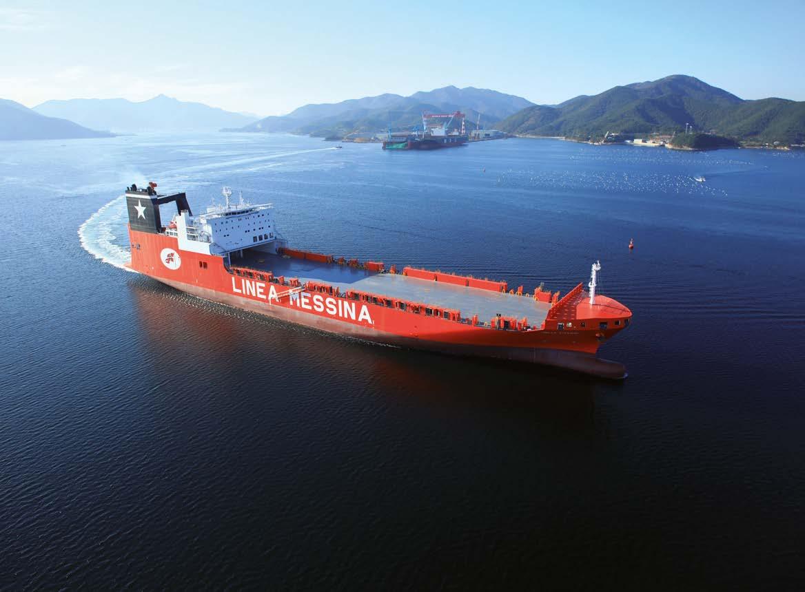
Jotun announced another new milestone for its Clean shipping commitment through a commercial agreement with the Italian ship owner Ignazio Messina & C. for Jotun’s Hull Skating Solutions (HSS). This collaboration reflects a shared vision for innovation and sustainability, positioning Messina to navigate even the most challenging trades.
The vessel Jolly Rosa will apply Jotun’s HSS, including the innovative HullSkater, developed in collaboration with Kongsberg, to ensure proactive cleaning as well as inspections on the hull. The solution combines high performing coatings, proactive monitoring and high-end technical service, with the HullSkater, also offering a clean hull guarantee.
“As a company with a long history of operating in complex and challenging trades, we are constantly seeking innovations and solutions that will benefit our operations in the long run. Jotun’s HSS will help us in the route towards more effective environmental sustainability targets.
Thanks to this agreement, our ships’ hulls will perform better and we are oriented to further implement these new innovative technologies,” said Andrea Gais, CEO of Gruppo Messina Spa and Chairman of Ignazio Messina & C. Spa.
Jotun’s customised proposal was well-received by Messina, who recognises the value of advanced hull protection and performance monitoring.
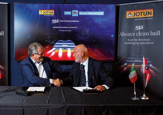
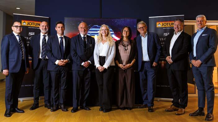
The agreement that was officially signed during a ceremony at Jotun’s headquarter in Sandefjord, Norway, adds to Messina’s portfolio of Jotun solutions on their fleet, having utilized various antifoulings as well as HPS from Jotun on other vessels.
“We are proud to support Ignazio Messina & C. in their clean shipping journey. Not only will HSS provide excellent in-operation hull performance, but it will also position Messina as an innovative partner with sustainability as a main focus for their customers,” said Giulia Nebbia, Area Sales Manager at Jotun.
With this agreement the total Jotun systems applied across the fleet of Ignazio Messina & C. is expected to avoid approximately 11,800 tons of CO₂ emissions annually, compared to market average products calculated based on ISO 19030. This adds to the overall efforts Jotun is contributing to the industry with. In 2024 alone, Jotun coatings helped customers avoid 11.1 million tons of CO₂ emissions, verified by DNV.
Messina will also benefit from Jotun’s HullKeeper program, enabling real-time performance monitoring and fouling risk
assessment. This empowers shipowners to make informed decisions, optimize fuel efficiency, and maintain a clean hull throughout the vessel’s lifecycle.
“Hull performance management is getting ever more important for fleet management; minimising hull resistance is the first step to improving the energy efficiency of the vessel in order to pursue environmental targets. Together with digital tools and monitoring systems, Jotun solutions will support our Technical Department in our decarbonization journey,” said Andrea Gais in Ignazio Messina & C.
Morten Fon, President and CEO of Jotun, added: “We are reliant on partners like Messina to be able to deliver on our mission: Helping the industry cut carbon emissions, preserve fuel and protect biodiversity. This agreement not only strengthens the partnership between Jotun and Ignazio Messina & C. but also sets a benchmark for cleaner operations in the maritime industry.
This inspires us to keep innovate and continue to deliver great solutions to the market.” ‹
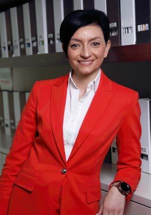
Prakul Rakesh, Director
InnMats Pvt Ltd – Navi Mumbai, India prakul.rakesh@innmats.com
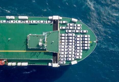
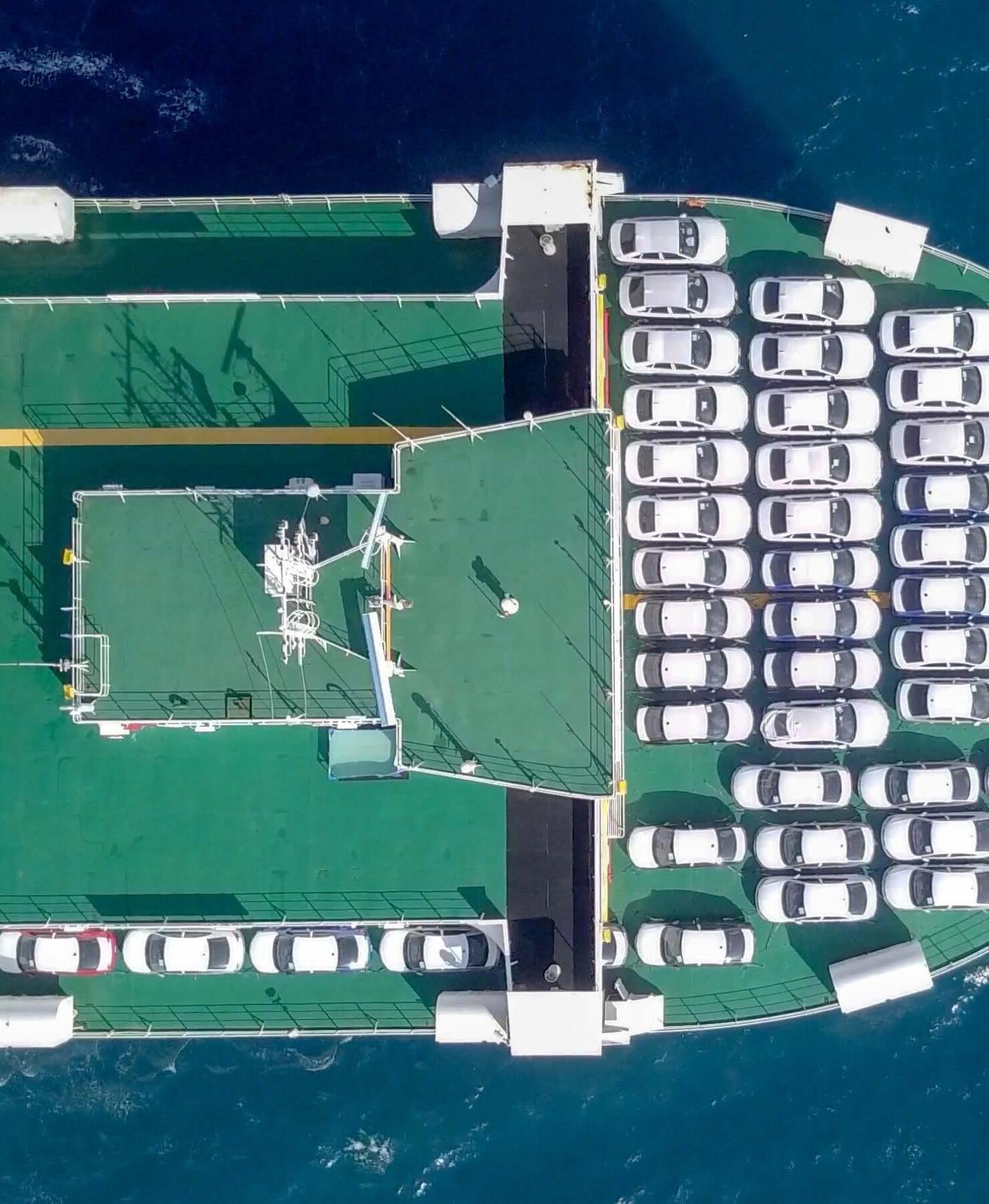
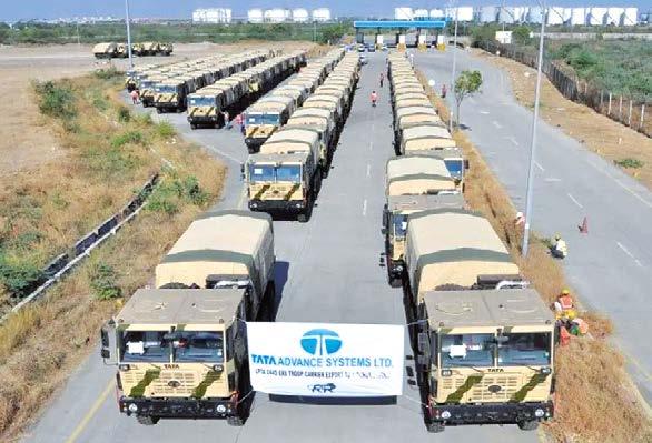
Asia is a major hub for automobile production and export, with countries like Japan, South Korea, China, India, and Thailand leading the charge. The region is known for its cost-effective manufacturing, advanced technology, and strong supply chains, which make it a key player in global vehicle exports. In FY 2023 (ended March 2024), approximate in total 14-15 million vehicles exported from Asia1. In FY 2024–25, exports surged to 16-17 million units, a 12–13% rise from FY24.
The rising trend of export vehicle shows clear market in future, however, one persistent challenge for exporters is corrosion - the silent enemy that can damage the vehicle’s structural integrity and aesthetics during transit.
Corrosion remains a key challenge for export vehicles, as it affects structure and appearance during transit.
This article explores the causes, risk factors, and preventive measures for corrosion in vehicles being exported from Asia.
Why corrosion occurs during export
Corrosion is a natural electrochemical reaction where metal reacts with moisture, oxygen, and salts, leading to rust formation. During export, the conditions are highly conducive for corrosion due to:
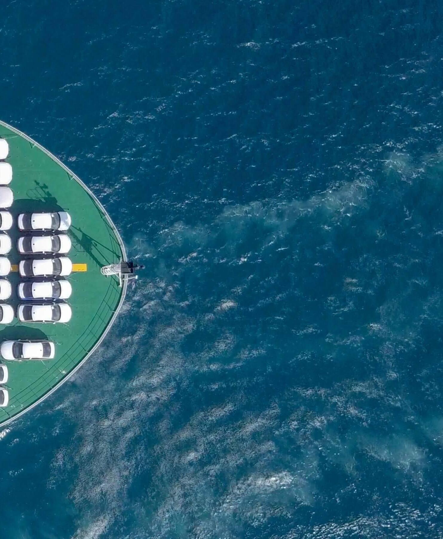
high humidity in coastal ports: most Indian ports (e.g., Mumbai, Chennai, Kochi, Vizag) are located in humid, salty coastal areas. Vehicles stored in open yards for even a few days may begin to show signs of corrosion
long transit times: shipping to distant markets (such as South America or Africa) may take 2–6 weeks, during which vehicles are exposed to salt-laden sea air, condensation in containers or ship decks, and fluctuating temperatures
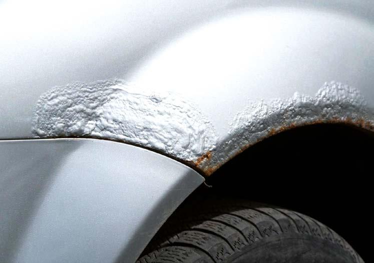
poor packaging or protective measures: vehicles exported without adequate protection (e.g., shrink wrapping, rust inhibitors, or VCI) are more vulnerable to surface oxidation, especially on exposed parts like brake discs, undercarriage and suspension, wheel hubs, and fasteners and battery terminals.
High-risk parts for corrosion in vehicles
Brake rotors & discs, often begin rusting even in storage
Undercarriage, exposed to salt spray and moisture
Electrical contacts: battery terminals and fuse boxes
Metal trim/emblems, cosmetic degradation
Engine bay components, especially aluminum parts in contact with dissimilar metals.
Vehicles treated with Nanocot have been shipped to the African market without any rust complaints. (Typically, sea shipments take 2–6 weeks, during which untreated vehicles often develop rust — but those coated with Nanocot remain corrosion-free.)
Consequences of corrosion for exporters
Customer rejection or warranty claims
Brand damage in new markets
Rework & refurbishing costs at destination
Reduced shelf life or roadworthiness of the vehicle.
Best practices to prevent corrosion in exported vehicles
Use of anti-corrosion coatings: apply protective coatings like wax-based underbody coatings, zinc-rich primer paints, and transparent anti-rust sprays on metallic parts
Vapour Corrosion Inhibitor (VCI) technology: use VCI covers or films for packaging, and place VCI emitters in the engine bay, cabin, and boot
Shrink wrapping & moisture barrier bags: full vehicle wrapping with UV-resistant plastic reduces exposure, and use desiccant bags inside containers to reduce condensation
Shipping in enclosed containers (for premium vehicles): protects from salt-laden air and reduces external contamination
Regular port inspection & storage under covers: ensure vehicles are stored in covered port sheds or under temporary tents, and weekly inspection for early signs of corrosion helps proactive treatment.
Anti-rust solution from the transit corrosion
Anti corrosion coating is one of the cost effective and durable solution among others. The use of protective coatings will not only protect the vehicle during shipping but also it increases the life of the vehicle while its usage.
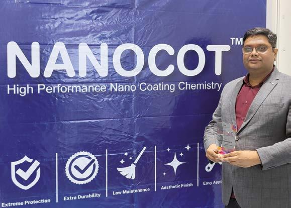
How Nanocot helps the OEM for vehicle exports
Nanocot is offered as an anti-corrosion clear coating. It is an advanced hybrid resin system, blend with polyurethane, polyurea, polysilane and nano-particles. Nanocot technology has been successfully applied on vehicles from one of the largest defence vehicle manufacturer from India. Nanocot 2K Matte was applied on the entire body, including rust prone locations (as observed by customer team). After long term field/ pilot tests and validation of Nanocot 2K showed no deterioration in extremely harsh shipping conditions, leading to extreme customer satisfaction of customer. Nanocot system was able to be completely remove the challenges faced and provided durable protection with Salt Spray Test of 2000 hours (ASTM B 117), QUV resistance of 2000 hours (ASTM D 4587) and Weatherometer test of 4000 hours (ASTM G115) to the vehicles. Nanocot 2K coating system also enabled TASL team to provided a 5-year warranty on the complete paint system to the foreign clients2. ‹
Introducing Evonik’s SILIKOPHEN® AC 4000, a revolutionary solvent-free and ambient-curing silicone resin that merges heat resistance with exceptional flexibility. This innovative product not only offers outstanding adhesion to various substrates but also ensures excellent corrosion protection and storage stability.
Perfect for tailored coating solutions, SILIKOPHEN® AC 4000 completes our range and meets diverse customer needs!
For more information on SILIKOPHEN® AC 4000, please download our new fact sheet!
Prakul Rakesh, Director of Innmats Pvt Ltd.
COVER STORY
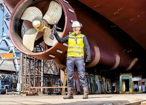
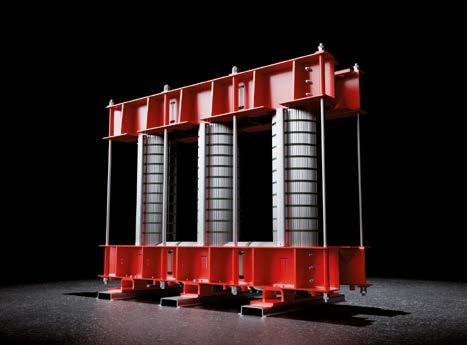
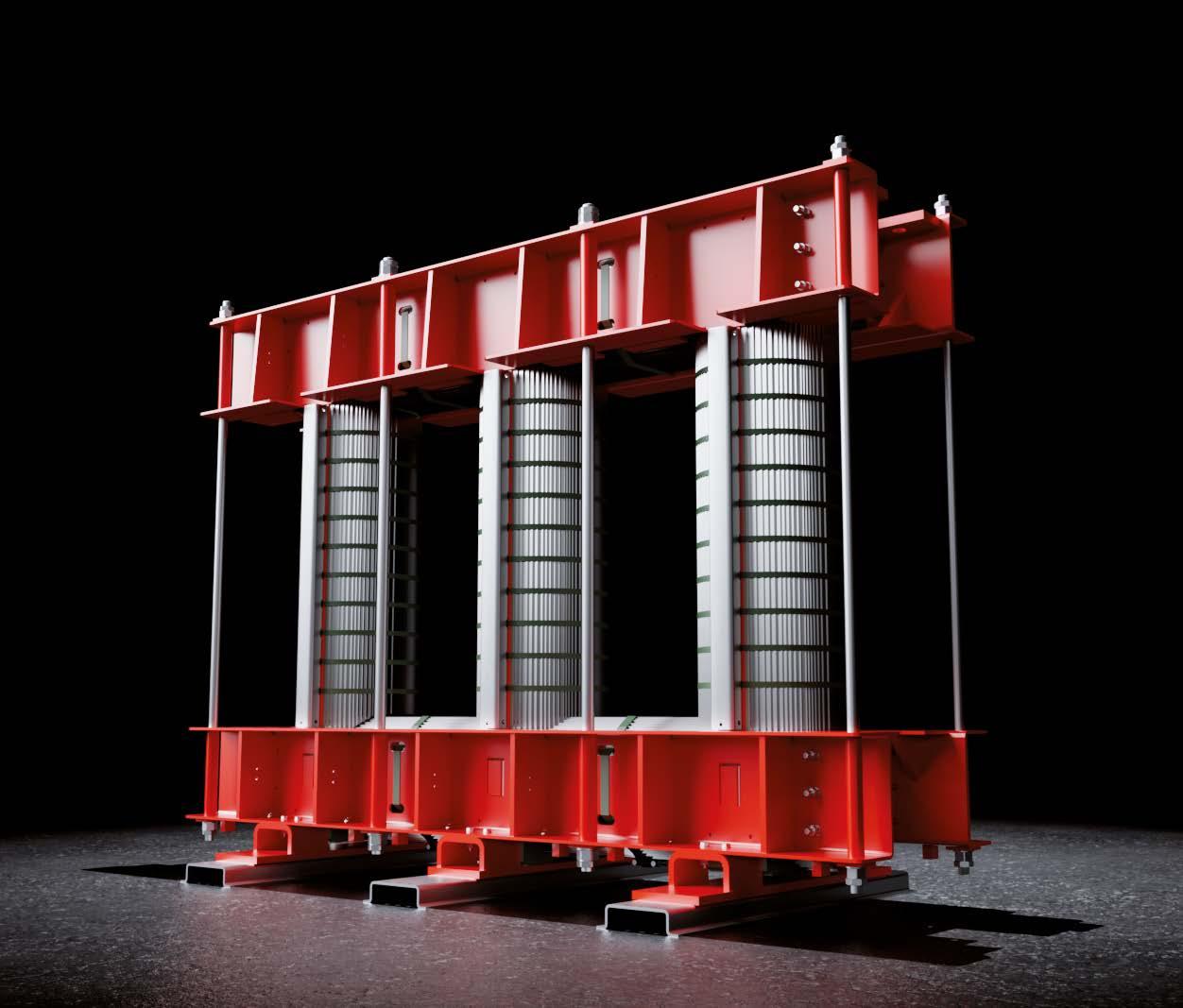
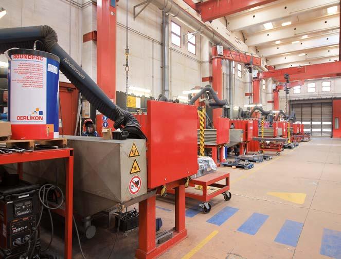
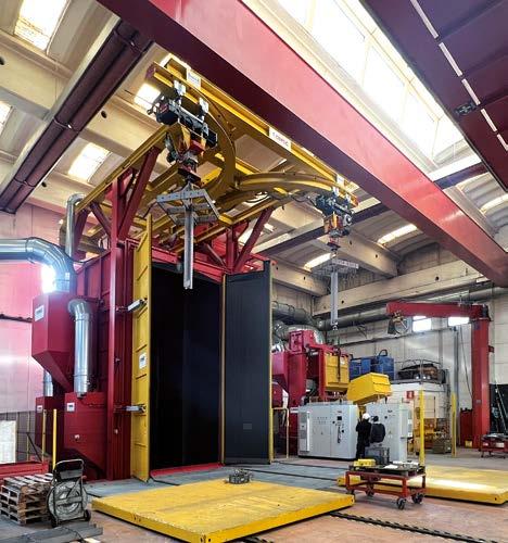
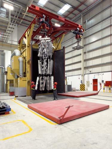
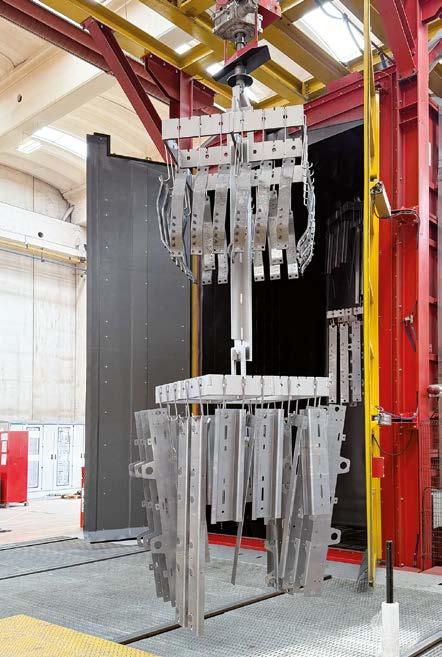
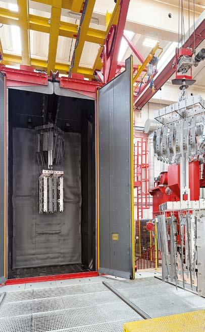
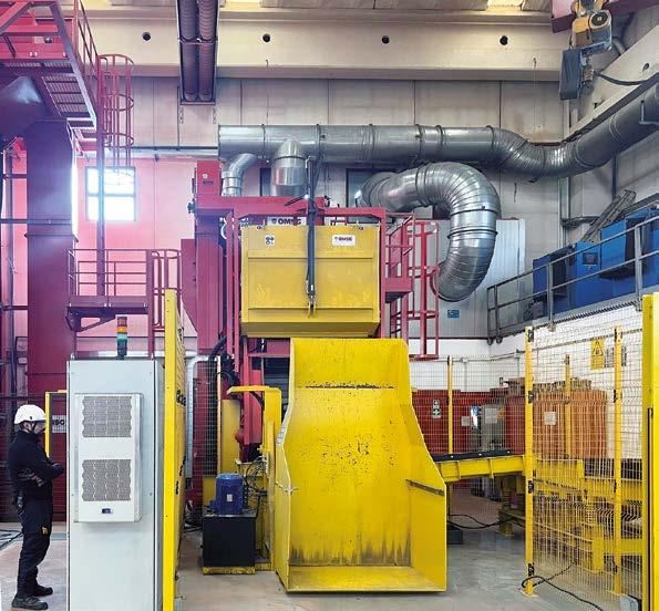
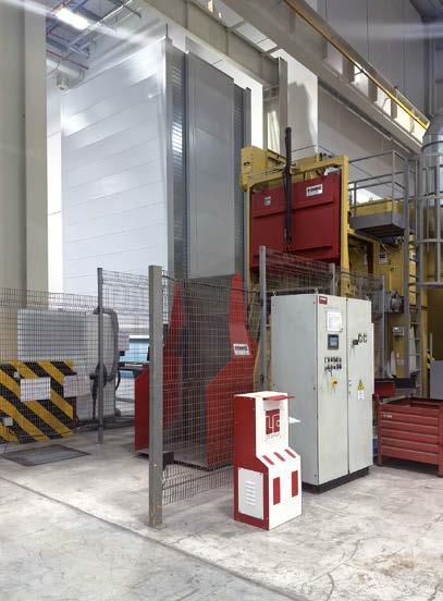
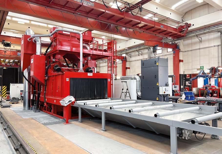
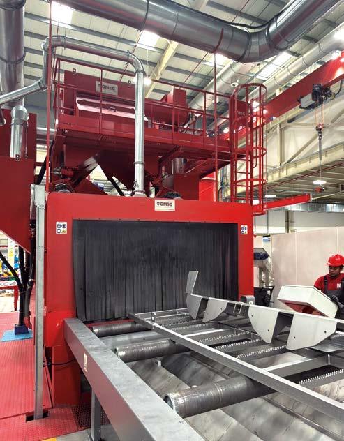
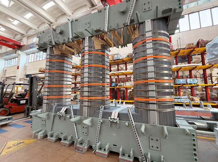
A MECHANICAL DEPARTMENT INTEGRATED WITH HIGH-EFFICIENCY SHOT BLASTING SYSTEMS: LTC’S CHOICE TO ENSURE THE DURABILITY OF ITS MAGNETIC CORES
Monica Fumagalli, ipcm®
Acomplex product manufactured using diversified production cycles in different plants: magnetic cores are the core business of LTC – Legnano Teknoelectric Company S.p.A., a global leader in the production of these components for a wide range of transformers and reactors. These are in fact the cores of transformers: they consist of electrical or magnetic steel laminations and are the fundamental element around which the primary and secondary electrical windings are arranged, guiding and concentrating the generated magnetic flux.
Various surface treatments can be performed on this type of product. Where required, a layer of insulating and protective paint is applied to the magnetic sheets to prevent oxidation without altering the material’s magnetic properties; the ideal paint type, its uniformity, and its controlled thickness are essential to reduce eddy currents and ensure durability. The standard steel metalworking that makes up the frame and core kit, on the other hand, can be galvanised and coated to increase the film’s anti-corrosive properties and, therefore, the surface coating’s durability. This is where mechanical pre-treatment by shot blasting plays a strategic role, improving coating adhesion and evening out the surfaces, thus ensuring long-term resistance and protection even under harsh operating conditions. For this project, LTC decided to rely on OMSG – Officine Meccaniche San Giorgio S.p.A., located in Villa Cortese (Milan, Italy), a few kilometres from its headquarters, which has been manufacturing shot blasting machines and automatic sandblasting systems since 1961.
The long-standing partnership between LTC – Legnano Teknoelectric Company S.p.A., which has been manufacturing magnetic cores for power transformers since the late 1950s, and OMSG – Officine Meccaniche
San Giorgio S.p.A., a supplier of shot blasting plants, has grown stronger over time and even extended to LTC’s production sites abroad.
Opening photo: Rendering of a magnetic core. LTC - Legnano Teknoelectric Company S.p.A. has been manufacturing magnetic cores for power transformers since the late 1950s.
Overview of Casa LTC: the architectural design for the renovation of Legnano Teknoelectric Company’s headquarters fully reflects its industrial and electrical culture.
Overview of the eight manual welding benches located near the shot blasting department.
LTC Group: from humble beginnings to industry leadership
The manufacture of magnetic cores has undergone profound changes over time, from the soft iron blocks used in the late nineteenth century to the forged or rolled soft steel that was insulated with paint or oxide in the 1930s, up to the standard magnetic sheet metal that emerged in the 1950s and is still used today in most transformers. It was in that decade, specifically in 1957, that Michele Bertelli began assembling his first small electrical transformers in his kitchen in Legnano (Milan), using steel and copper sheets. By 1960, he was producing one hundred transformers a day. These were the first steps of a company set to experience exponential growth until the turning point in 1992, when it decided to convert its production from transformers to magnetic cores, leveraging the experience gained in designing and manufacturing these products for the local market. “Today, we boast an international presence in over 120 countries,” explains Stefano Visentin, Industrial Engineer at the company, “and a leading market position with production sites in Italy, the United Arab Emirates, Taiwan, and soon, Canada, with approximately 1,100 global employees and 12,000 m/month of processed material.”
The philosophy of the LTC Group is based on a relentless pursuit of excellence through attention to every detail in the production of high-quality magnetic cores for a wide range of transformers and reactors intended for various applications: power generation, transmission networks (smart grids, HVDC links, high-voltage shunt reactors), distribution (dry and oil applications), traction in the railway sector, and special applications (e.g. data centres, shielding systems, and instrument transformers). The company’s strategy is complemented by a strong commitment to clean energy, reflected in LTC’s
The CAPRI 30/60 H25 hoist shot blasting machine at the Legnano site and, alongside it, its twin system installed at the Dubai site.
This shot blasting machine is used for medium-sized parts and is equipped with two hoists lifting parts up to 5,000 kg.
The Tappeto Rampante® system installed in Legnano and, alongside it, the shot blasting machine with the same characteristics installed in Dubai.
structured path to reduce CO2 emissions by 30% by 2030 and in its production specifically intended for the clean energy industry.
“We manufacture magnetic cores for transformers with all outputs and voltages, all types of cooling systems, and all operating modes,” emphasises Daniele Bertelli, the owner of the company together with his brothers Aurelio and Gianluigi. “However, our focus is on the green energy sector. We supply magnetic cores for transformers for the wind power industry (TSN for onshore and TSF for offshore applications), photovoltaic power plants, hydroelectric plants, cogeneration plants, and biomass plants.”
The global production network
LTC - Legnano Teknoelectric Company S.p.A. is located between the municipalities of Legnano and San Giorgio su Legnano. Its entire range of operations, from the longitudinal cutting of magnetic steel sheets to the production of steel components for the assembly of finished cores for transformers, is carried out in over 60,000 m² of covered facilities. In Italy, the Group has five plants employing 650 people, of which four are devoted to magnetic cores and one to metal components, with a sixth due to start construction next year. In Dubai (United Arab Emirates), LTC operates two plants covering an area of over 30,000 m², which were launched between 2011 and 2012 with the same production structure and, in particular, the same OMSG shot blasting systems used at the Legnano site. The Taiwan site has been operational since July 2023, and a new greenfield plant is under construction in Canada.
THE PHILOSOPHY OF THE LTC GROUP IS BASED ON A RELENTLESS PURSUIT OF EXCELLENCE THROUGH ATTENTION TO EVERY DETAIL IN THE PRODUCTION OF HIGH-QUALITY
This latest strategic investment will ensure maximum technological and organisational control, integrating the lean approach introduced by the Group around fifteen years ago with state-of-the-art machinery.
One of the most significant aspects of this strategy is the principle of keeping production close to customers to ensure reliability and stem competition in different markets. “This is much appreciated by our international customers, from Hitachi to Siemens and General Electric. In addition, our factories operate multi-brand systems coordinated by an MES system connected to all control platforms, providing continuous visibility of production, automated data collection, and real-time reporting. With sites in different geographical areas, we manage scheduling by also considering time zones and ensuring total resource sharing. Being able to show customers our fully integrated cycle aimed at maximum efficiency is critical, and the shot blasting operations we have already insourced and the coating process we intend to insource are preparatory to this goal.”
LTC’s industrial concept applied to architecture
During our visit, we had the opportunity to enter the company’s longest-standing factory (Plant 2), which was developed around the original Bertelli family home and is now divided into five halls,
including one devoted to shot blasting, and Plant 3, which houses the magnetic core machining departments and a new office area. The architectural design of the latter fully reflects LTC’s industrial and electrical culture, as Daniele Bertelli explains: “The building is completely clad in a noble material, copper, because one should be able to perceive its importance already while approaching the entrance gate. We do not sell iron products, but rather electrical performance, efficiency, energy savings, quietness, and ecology –all values carried by grain-oriented electrical steel, a special silicon steel that improves the magnetic properties of materials. The copper cladding of this building resembles the external winding of a transformer and represents our history, whereas inside, just like in the heart of a transformer, there are the people who design and manufacture our cores. We also wanted to give it a name other than the traditional ‘headquarters’: we called it Casa LTC (or ‘LTC House’) precisely to convey this sense of belonging and familiarity.”
Strategic shot blasting for kit preparation
In Plant 2, the preparation of the structural framework and kits takes place. The buildings of this plant also house a technologically advanced mechanical workshop and a department dedicated to component welding. The metalworking operations include laser or plasma cutting of flat sheets in medium-carbon steel. “We
The LAUCO 2010/8 roller conveyor shot blasting machine installed at the Legnano site.
The roller conveyor system installed at the Dubai site for shot blasting sheets up to 18 m in length.
The dimensions and weight of the treated magnetic cores range from 50 kg to 200 tonnes, whereas metalwork structures account for about 10% of the total weight handled, on average.
From left to right:
perform shot blasting with three automatic systems, selected according to the size of the workpieces, before and after welding,” explains Lorenzo Mendicino, the Plant Manager of Plant 2. “The first phase serves to remove oxide and scale after cutting and aims to avoid contaminating the emulsified water used in the machines. The second phase, on the other hand, is performed after welding and prepares the surfaces for the subsequent galvanising and/or coating operations (which we outsource) by improving the adhesion of the protective layer. Another important process is the rounding of edges using dedicated automated systems, an essential detail in our sector, as rounded edges are considered an indicator of quality. Indeed, our goal is to maintain the highest possible level of quality to offer the best product on the market.” The cleaner the surfaces, the greater the coating adhesion, a determining factor for durability, especially for components intended for harsh conditions, such as marine corrosion or direct exposure to atmospheric agents.
Plasma cutting, used for thick steel sheets, requires a subsequent cleaning phase, carried out primarily with an OMSG LAUCO 2010/8 roller shot blasting machine. The use of this equipment ensures higher processing quality for the downstream operations.
THE CLEANER THE SURFACES, THE GREATER THE COATING ADHESION, A DETERMINING FACTOR FOR DURABILITY, ESPECIALLY FOR COMPONENTS INTENDED FOR HARSH CONDITIONS, SUCH AS MARINE CORROSION OR DIRECT EXPOSURE TO ATMOSPHERIC AGENTS.
LTC’s shot blasting machine fleet
“We have supplied LTC with three shot blasting plants at this site and three identical plants at the Dubai site,” illustrates Enzo Dell’Orto, the CEO of OMSG. “These are a CAPRI 30/60 H25 hoist shot blasting machine, an SG6 H2 Tappeto Rampante® steel belt tumblast shot blasting machine (both installed in 2019), and a LAUCO 2010/8 roller conveyor shot blasting machine installed in 2023.”
In more detail, the CAPRI system is equipped with two hoists that lift parts up to 5,000 kg. It uses seven turbines, each with a power of 11 kW, to shot blast components with a maximum diameter of 3,000 mm and a height of up to 6,000 mm, which are rotated within its chamber.
The Tappeto Rampante® steel belt tumblast shot blasting machine has a 600-dm³ capacity and a maximum throughput of 2,000 kg, and it is designed for treating small parts. “Its peculiarities,” notes Dell’Orto, “include the two-cylinder hydraulic skip loader and the part unloading system using a vibrating channel.”
The LAUCO 2010/8 roller conveyor system, parallel to the plasma cutting machine, has a 2,000 mm-wide and 1,000 mm-high shot blasting section, eight 11-kW turbines, and 9-metre inlet and outlet roller conveyors. It is also equipped with a brushing and blow-off unit at the outlet to remove any abrasive residues from the parts. “We also design all our plants in accordance with Industry 4.0 parameters,” states Dell’Orto.
Conclusions
Bertelli emphasises: “We were so pleased with the performance of the OMSG systems that, when it came to duplicating our production system at the site in Dubai, we requested the same set of shot blasting machines. This confirms the attention we devote to every detail of LTC products, from their cases to their systems’ heart, the magnetic core.”
Today, Legnano Teknoelectric Company is experiencing unprecedented growth, with orders already scheduled until 2026. “This has never happened before in our history. It proves we are working in the right direction. We also have numerous projects underway or in the start-up phase to further boost our production, and they will most likely involve our partner OMSG once again – whose geographical proximity to our location is undoubtedly a further added value to our long-standing collaboration,” concludes the owner of LTC. ‹
"WE WERE SO PLEASED WITH THE PERFORMANCE OF THE OMSG SYSTEMS HAT, WHEN IT CAME TO DUPLICATING OUR PRODUCTION SYSTEM AT THE SITE IN DUBAI, WE REQUESTED THE SAME SET OF SHOT BLASTING MACHINES. THIS CONFIRMS THE ATTENTION WE DEVOTE TO EVERY DETAIL OF LTC PRODUCTS, FROM THEIR CASES TO THEIR SYSTEMS’ HEART, THE MAGNETIC CORE.”
From left to right: LTC owner Daniele Bertelli, OMSG CEO Enzo dell’Orto, and Stefano Visentin from LTC in front of one of the three Berlin Wall pieces on display outside Plant 3.
These finned-tube air coolers were recovered as part of an important public project in a waste-to-energy facility.
SUCCESS STORY
Säkaphen and Donelli: joining forces for heat exchanger protection
This is the story of how an Italian company was selected by one of the largest civil engineering and construction companies in Europe for its excellent heat exchanger protection service.
Säkaphen (Gladbeck, Germany) and Donelli Alexo, part of Gruppo Donelli (Legnano, Italy), have been partners for over 20 years now: the former as a manufacturer of anticorrosion and protective coatings and the latter as an applicator of high-performance solutions for safeguarding assets. Together, they have decades of expertise in the most diverse industries, including heat exchangers, tanks, pipelines, and highvoltage insulators, across various environments, from marine areas to refineries, worldwide.
Gruppo Donelli, in particular, maintains strong ties with the French market. “Recently, this has led us to land a significant order from one of the largest civil engineering construction companies in France (and Europe), which we tackled using one of Säkaphen’s flagship products to ensure outstanding results,” explained Alessandro Vanacore, Head of Technical Sales at Donelli Alexo.
Project specifications
As part of an important public project in a waste-to-energy facility with strict requirements in terms of both performance and documentation, the task involved reapplying a protective coating on 6 finned-tube air coolers. The systems were 6 m long, 1 m high, and 0.5 m wide. As they were used for cooling down fumes at an operating temperature of 140 °C (230 °C Tmax), their surfaces were contaminated with oils and grease, which posed a risk of clogging their finned tubes and, therefore, causing a loss of performance or even plant stoppages. Gruppo Donelli was thus required to clean and re-coat them to restore their original functionality and extend their service life.
How Gruppo Donelli worked
Gruppo Donelli started with a chemical cleaning phase of the air coolers to remove oil, grease, and any other contaminants. “The specific surface preparation process implemented is the result of years of experience and extensive testing with a specialist partner to define the best possible treatment protocol,” pointed out Vanacore. Simultaneously, casings and manifolds underwent dry cleaning with micro glass beads. “Finally, we applied a protective coating from Säkaphen in 3 layers, performing the necessary intermediate and final polymerization stages to achieve the required dry film thickness of 75 µ.”
Säkaphen’s coating solution
“The protective product chosen for this high-stake project was Si 14 E, one of our flagship products,” noted Christoph Fischer-Zernin, Commercial Director at Säkaphen. This is a one-component, phenolic-based, thermosetting coating with excellent hydrophobic properties and chemical resistance to organic and inorganic acids, salt solutions, aliphatic and aromatic hydrocarbons, fume gases, alcohols and cooling water. It is also resistant to temperature fluctuations and forms a very hard yet elastic surface that effectively prevents caking, fouling, and incrustation.
“For the customer, this meant that the 6 finned-tube air coolers could be quickly brought back into service, perfectly restored, protected, and ready to ensure many further years of smooth operation, with clear financial but also environmental benefits,” Fischer-Zernin stated with great satisfaction. “We could not offer such a service of excellence without our authorized applicators worldwide, and Gruppo Donelli is one of our longest-standing and most trusted partners.” ‹
Left photo: applying Säkaphen Si 14 E on a finned-tube air cooler.
A finned-tube air cooler protected with Si 14 E.
VISCO-ELASTIC TECHNOLOGY: A MONOLITHIC, AMORPHOUS COATING TRANSFORMING PIPELINE PROTECTION
Edwin Welles, Denso North America – Houston (TX), United States info@densona.com
Pipelines play a critical part in supporting our way of life. In the USA alone there are a total of 3 million miles of natural gas pipelines [1], and 2.2 million miles of water pipelines [2] supporting the infrastructure to fulfil our demands in basic functions we take for granted daily such as available energy and water. The infrastructure is aging, however: for example, over 50 percent of the pipelines were built in the USA 40 years or longer ago. Without coatings and cathodic protection systems, the majority of this infrastructure would have to be replaced by now. The cost to rebuild pipeline networks would be astronomical; that is why companies and governments invest in protecting their pipelines to extend the life of these assets as long as possible.
The total market globally for pipeline coatings was valued at 8.4 billion dollars in 2024 [3] and is expected to grow to 15.1 billion dollars by 2033 [3]. New technologies such as Visco-elastic coating systems have established markets in niche areas within this industry such as replacing or repairing old pipe coatings, coating weld seams at new pipeline projects and coating transitions between underground and aboveground pipelines (soil-air interface). Market share and revenues have grown rapidly over the past two decades and are expected to keep growing due to the versatility, easy application, cost savings, and technology awareness by a broader audience. This article will help explain the benefits and the cost savings this technology has brought to the market.
The evolution and innovation of visco-elastic technology History
Originating from a waterproofing concept, Visco-elastics were designed to stop water on a molecular level. Corrosion cannot occur without water, not even microbiological incurred corrosion (MIC).
The elimination of water on a molecular level is the essential concept of the Visco-elastics and was developed in the 1990s with support of a major gas and oil company in the Netherlands. After trials and long-term testing, confirming the proof of concept, the products went to market. Multiple patents were granted to different manufacturers over the years. In 2016, international standards such as the International Standards Organization (ISO) added this successful technology giving credibility and setting minimum requirements for the products on the market and for any new products to come. Currently standards such as ISO 218093:2016, ISO 21809-11:2019, AWWA C232:2022, NACE SP 0109:2019 and CSA Z45:32 have been in place to safeguard the technology and to assist end users with its use.
Bonding on a molecular level
The polymers of a Visco-elastic coating adhere by van der Waals bonding and have a continuous wetting effect on the surface. The distance between the coating polymers and the steel substrate is extremely small (10-9 m) as van der Waals bonding occurs on a molecular level between the two materials (electron affinity/ interaction). Examples of other materials that show wetting and van der Waals bonding on a substrate are oil and grease: they are well bonded and without a solvent, they are very difficult to remove from the surface. Figure 1 shows a microscopic image of a visco-elastic product adhering to the surface via van der Waals bonding, demonstrating the close interaction of the coating and the substrate.
Due to a low surface tension, Visco-elastics adhere to steel, and most common materials (PE, PP, Bitumen, Epoxy, Urethanes, Coal Tar) used in the industry, creating a seamless transition and are therefore easily integrated into existing pipeline networks.
Monolithic self-repairing coating
Unlike oil and grease, Visco-elastic coatings present both liquid behaviour and rubbery behaviour, carefully designed, to fulfil coating functionality. The design allows for unique features such as self-repair (Fig. 2) when indentations or even small damages occur, and an easy application creating a smooth, monolithic layer, conforming itself entirely to the substrate without any stress.
Figure 2 - The design enables unique features such as self-repair in the event of indentations or minor damages, as well as an easy application that creates a smooth, monolithic layer, fully conforming to the substrate without stress.
Figure 1 - Microscopic image of a visco-elastic product adhering to the surface through van der Waals bonding, illustrating the close interaction between the coating and the substrate.
ADVANCEMENTS
An example of the manual application of a Visco-elastic coating on a large pipe surface with spiral welds demonstrates excellent coverage (Fig. 3). The coating conforms perfectly to the surface, bonding on a molecular level, which prevents water molecules from penetrating. This results in a monolithic layer with complete adhesion, ensuring the coating is entirely watertight. Such applications often undergo rigorous testing, such as peel strength tests following standards like ISO 21809-3:2016. The unique properties of a Visco-elastic coating are nowadays included in the minimum requirements of various international standards and specifications of leading oil and gas, utility and water companies. The recognized, successful technology with its unique properties and benefits established itself over the
past decades and demand is growing rapidly due to the ability to have new solutions for pipeline owners and to replace older, traditional coating systems with a longer lasting, easy to apply, and clean coating system. Traditional systems such as tapes and shrink sleeves require most often a higher level of surface preparation and may require primers, while installation is more sensitive to application errors. Shrink sleeves are applied by heating the product with for instance a torch, while tapes are applied under tension (preferably with a machine). Besides safety concerns, the applications are therefore more sensitive which may result in disbondment and overlap issues. Liquid coatings such as epoxies or polyurethanes often need a perfectly clean surface (SSPC 10), are sensitive to humidity and temperature changes, and require drying time. Visco-elastics address this by an easy-to-apply conforming inner layer (hand-applied with no tension) with lower surface preparation requirements (SP-2/ SP-3), while having no primers, solvents or drying time. The easy, safe and clean application creates a better environment to do a proper installation of the coating and minimizes risks of failures.
Visco-elastics are compatible with existing and previous line pipe coatings such as coal tar, 3LPE, 3LPP, urethanes, bitumen, etc..
Visco-elastics have many advantages for in the field applications such as pipe coating rehabilitation, pipe crossings, soil to air interfaces, field joints (girth welds) both on- and offshore, t-s and elbows, and more.
Case histories
Gulf Coast Countries (GCC) such as Saudi Arabia, United Arab Emirates and Oman are faced with aggressive soil (Sabkha soil) in the coastal areas: due to tide, sea water sometimes travels over a mile inland, depositing salt and sulphuric compounds into the desert sands, creating a wet and dry cycle. The salinity concentration of the top surface may reach over 30% (which represents concentrations of salt present in dust) while the brine salinity of the water table can go as high as 18 %. Lab testing according to international standards utilizes salt concentrations similar to sea water (3%), therefore not representable for circumstances like these.
During application, a sandblasted clean pipe can be contaminated with salt by flying dust within hours. Coatings sensitive to osmosis will not survive, while surface preparation requirements limit many coatings in the market. End users prefer long term trials to qualify coatings for these regions. In 2011, a Visco-elastic coating (Viscotaq) was applied on a 42 inch main line and inspected after 15 months.
The coating remained in excellent shape, there was no corrosion and no disbondment observed at the inspection. Figure 4 represents an image taken during application: salt crust, water
Figure 3 - Manual application of a visco-elastic coating on a large pipe surface with spiral welds, showing excellent coverage.
Figure 4 - Image taken during application, showing the salt crust, water table, and intermediate soil area.
table and intermediate soil area are clearly visible. The inspection results after 15 months showed not only complete adhesion on the surface but also the uniform, continuous behaviour of the coating (with no overlaps present, forming a single, cohesive layer). Visco-elastics have proven to be successful and have saved end users in the GCC region tens (if not hundreds) of millions of dollars in repairs and maintenance. Another long term review of applied coating showed excellent performance of a Visco-elastic in aggressive clay areas where the elastic component (rubbery behaviour) allowed for resilience against shear.
After installation in 2012 on various diameters of pipelines running at an operating temperature between 40 and 50 degrees Celsius, inspection took place after two years: no corrosion was observed, 100% adhesion and consistent thickness readings at various clock positions (Fig. 5). Note that the Visco-elastic type of coating was the semi-solid technology having added benefits in these circumstances, which is discussed in the next paragraph. The coating rehabilitation program continued for a number of years and the end user was able to improve their integrity system saving millions of dollars in recoating programs. No recoating was ever needed up to date and compared to their traditional system (which showed deterioration sometimes even after five years), the service-life has been close to tripled by choosing a Visco-elastic system.
THE INSPECTION RESULTS AFTER 15 MONTHS SHOWED NOT ONLY COMPLETE ADHESION ON THE SURFACE BUT ALSO THE UNIFORM, CONTINUOUS BEHAVIOUR OF THE COATING (WITH NO OVERLAPS PRESENT, FORMING A SINGLE, COHESIVE LAYER).
Diversity has a face.
Our flexible system coating solutions – as exclusive as your requirements
Currently the coating is in mint shape and continuous to add beneficial years of service free of charge each year.
Summarized, many clients globally have saved millions of dollars over the past decades profiting from the benefits of the Viscoelastic technology where most importantly their assets are preserved, reliably extending service-life with a clean, easy to apply, long term solution.
Technological advancements
Even though the visco-elastic technology is seen as relatively new, it has been on the market for 30+ years. In 2009, a new improved visco-elastic coating was developed (Viscotaq), improving stability at elevated temperatures and at vertical applications, and adding more resilience to soil stress and other mechanical influences. Unlike existing visco-elastics, which are more or less semi-liquid, and therefore more dynamic, Viscotaq came with the concept of a semi-solid advancement allowing for more stability to prevent sliding at verticals, and differences in thicknesses over time at elevated temperatures. Additionally, the proprietary patented polymer formulation shows high stability by semi-solid behaviour up to 130 degrees Celsius and more resilience against mechanical influences such as soil stress caused by movement of the pipe (temperature expansion, movement after installation).
Current limitations of visco-elastic coatings and future developments
Visco-elastic coatings are mostly hand-applied which makes the technology ideal for in the field applications. Applications are limited to stretches of pipe rather than coating an entire (new)
pipeline. New developments by Denso however have made it possible to supply the market with a cost effective, long-term line pipe coating for the oil and gas, water, and off-shore industry (Fig. 6). Previously, high temperature applications (above 95 degrees Celsius) were a limiting factor. Since they have become of more interest to end-users, visco-elastic systems such as the Viscotaq XHT system were developed over the past years to meet this demand and are currently commercially available and in service by leading oil companies.
Conclusion
Visco-elastic coatings offer the industry an innovative, new approach in solving corrosion problems, combining advanced polymer technology with practical benefits like durability, cost savings, and environmental sustainability. As industries incorporate these innovations, pipeline networks are better protected, creating a safe and reliable infrastructure. Whether in oil and gas, utilities or water, visco-elastic coatings have a transformative impact on pipeline integrity management for generations to come and benefit the industry and our way of life as a whole. ‹
References
[1] Natural gas pipelines - U.S. Energy Information Administration (EIA)
[2] Water Infrastructure | ASCE's 2021 Infrastructure Report Card
Figure 5 - Inspection after two years of service showed no corrosion, 100% adhesion, and consistent coating thickness at various clock positions.
Figure 6 - New developments by Denso provide a cost-effective, long-term line pipe coating for the oil and gas, water, and offshore industries.
The forum for the corrosion protection community, exploring pipeline coatings, hydrogen transportation, new technology and markets
Highlights from the 2026 agenda
Panel discussion Evening Networking event
Papi Diambu
Mbikay
Specialist Materials
Technology
Equinor
9 sponsors and exhibitors
Industry-leading speakers include:
Denis Melot
Expert Non-Metallic Materials & Coatings
TotalEnergies
Nicolas Singling
Paintings, Coatings & Non-Metallic Materials, Discipline Lead Engineer
SAIPEM
Also sponsored by:
Expert speakers
Jeff Rogozinski
Global Market Director –Functional Coatings
Sherwin Williams
Media Supporters:
This study evaluates the performance of a patented hybrid galvanic anode system engineered to integrate the advantages of both impressed current (ICCP) and sacrificial anode (SACP) cathodic protection methods. The system is designed to provide a high initial polarization phase, followed by long-term, self-sustaining galvanic protection. Reinforced concrete specimens were prepared with either conventional zinc anodes or the proposed hybrid anodes and monitored over approximately ten months (≈ 7000 hours), with potentials recorded hourly. Prior to electrical connection, both cathodes exhibited similar active potentials (around −500 mV vs. copper/copper sulfate reference electrode, CSE), while the hybrid anode displayed a considerably more negative open-circuit potential (≈ −1.17 V vs. CSE), providing an additional driving voltage of about 226 mV compared with the conventional system. Upon circuit closure, the hybrid configuration produced a stronger initial polarization (≈ −720 mV vs. CSE) and maintained higher protection current during the early activation phase.
Introduction
Corrosion of steel reinforcement in concrete remains one of the most persistent and costly challenges affecting the durability and safety of civil infrastructure worldwide. When aggressive ions such as chlorides penetrate the concrete cover and destroy the passive oxide film on the reinforcing steel, corrosion begins. The resulting corrosion products occupy a much greater volume than the original steel, generating internal stresses that lead to cracking, delamination, and eventual structural degradation. According to the Federal Highway Administration, cathodic protection (CP) is the only rehabilitation method that has been conclusively proven to stop corrosion in chloride-contaminated reinforced concrete, regardless of chloride concentration [1]. Because corrosion of reinforced concrete structures poses both safety risks and significant maintenance costs, the continued development of more efficient, reliable, and durable CP systems remains essential for extending the service life of critical infrastructure and ensuring sustainability for future generations. There are two primary forms of cathodic protection: impressed current cathodic protection (ICCP) and sacrificial anode or galvanic cathodic protection (SACP). When properly designed and installed, both systems effectively mitigate corrosion by providing protective current to the reinforcing steel. In ICCP systems, current is supplied from an external DC power source through inert anodes. In contrast, SACP systems use the electrochemical potential difference between dissimilar metals, such as zinc and steel, to create a protective current without the need for external power.
Although ICCP systems offer precise control and can deliver high protection currents, they also involve several challenges. The requirement for external rectifiers, wiring, monitoring devices,
and continuous power supply increases both installation and maintenance costs.
Additionally, maintaining proper current distribution in complex geometries and varying exposure environments can be difficult. Variations in temperature, humidity, chloride content, and concrete resistivity may lead to overprotection—causing hydrogen embrittlement, coating disbondment, or excessive alkalinity— or underprotection, allowing corrosion to continue. These operational complexities often limit ICCP adoption in smaller or difficult-to-access structures.
On the other hand, galvanic systems provide a simpler and more maintenance-free solution. Galvanic anodes typically consist of a zinc core electrically connected to the reinforcing steel through wires or metallic straps, surrounded by an activated backfill or precast mortar designed to enhance ionic conductivity. Once installed, the zinc anode corrodes preferentially, supplying protective current to the embedded steel. Discrete galvanic anodes are often used in patch repairs to mitigate the “ring” or “halo” anode effect— where newly repaired, cathodic regions accelerate corrosion in surrounding, unrepaired zones. Initially, these anodes deliver a high current to repassivate the adjacent steel, with the current gradually declining as equilibrium is achieved [2].
Recent advances in cathodic protection technology have sought to combine the controllability of ICCP systems with the simplicity and self-sufficiency of galvanic systems through hybrid cathodic protection designs. In such systems, an initial phase of impressed current rapidly re-passivates steel and redistributes chlorides, followed by long-term galvanic protection without external power or complex circuitry. These hybrid configurations aim to overcome the inherent limitations of both conventional ICCP and SACP systems.
Building upon these developments, a new class of dual-stage galvanic anodes has emerged, capable of delivering both immediate and sustained corrosion protection through optimized electrochemical design and material selection. Enhanced backfill formulations ensure consistent ionic conductivity and controlled activation, reducing the risk of passivation and enabling reliable long-term performance. Moreover, recent field and laboratory investigations have demonstrated the benefits of staged or delayed activation, wherein different anodes within a network are programmed to activate at predetermined intervals. Such staged operation provides adaptive current output over time, matching the evolving protection needs of the structure and significantly extending system lifespan.
Together, these innovations represent a substantial advancement in sacrificial anode technology, achieving a balance between durability, performance, and simplicity. The integration of staged activation, improved backfill chemistry, and optimized anode design offers a smart, self-regulating system that delivers performance comparable to ICCP while retaining the inherent reliability and low-maintenance advantages of galvanic protection. The aim of this article is to present and evaluate the performance of a new generation of dual-stage galvanic cathodic protection systems for reinforced concrete structures. The study examines their electrochemical behavior, current output characteristics, and long-term stability through a combination of laboratory investigations and extended field exposure. The methodology includes comparative performance assessments under controlled environmental conditions, continuous monitoring of current density evolution over time, and evaluation of protective
effectiveness using electrochemical potential measurements and corrosion analyses. It should be noted that the tests presented in this study were conducted on small-scale specimens, where each anode protected a limited surface area. Complementary tests on larger specimens and real structures are currently in progress to verify whether similar electrochemical behavior and protection efficiency can be achieved under field-scale conditions. The results are intended to demonstrate the feasibility of adopting this advanced, maintenance-free protection system as a practical and sustainable alternative to conventional CP methods.
Methodology
Concrete specimens with dimensions of 200 × 150 × 100 mm were prepared, as illustrated in Figure 1. Each specimen contained a deformed steel reinforcing bar with a diameter of 10 mm. To prevent end corrosion and ensure a defined exposed length, both ends of each rebar were coated with epoxy resin, leaving 180 mm of the central portion embedded and exposed to the concrete environment.
The concrete mix was prepared using ordinary Portland cement, with the mix proportions summarized in Table 1. Sodium chloride (NaCl) was added to the mixing water at a dosage of 2% by weight of cement to introduce chloride ions (Cl-) into the concrete, resulting in an overall chloride concentration of approximately 1.2% by weight of binder. This chloride content was selected to simulate the corrosion conditions typically encountered in marine environments. Two sets of specimens were cast: one incorporating conventional galvanic anodes (control group) and the other containing novel hybrid galvanic anodes.
Figure 1: Schematic of concrete samples for checking corrosion and applying cathodic protection.
After casting, all specimens were cured by immersion in saturated limewater for 28 days to ensure complete hydration. Upon completion of curing, the free corrosion potential (Ecorr) of the embedded steel was measured in accordance with ASTM C876-15 [3]. Measurements were recorded using a data logger operating at a frequency of one reading per hour over a monitoring period of approximately ten months. Following the initial potential assessment, galvanic cathodic protection (CP) was applied to the relevant specimens using discrete sacrificial anodes embedded in the concrete. The steel reinforcement was electrically connected to the zinc-based anode using insulated copper wiring, thereby establishing the galvanic CP circuit.
There are over 10,000 Level I, II and III inspectors in 74 countries worldwide, as large clients consider the qualification of Coating Inspector Frosio as a reference for monitoring the quality of the application of a painting cycle.
There are 367 active Certifications in Italy, of which 109 Level I (white card), 115 Level II (Green card) and 143 Level III (red card). The certification is in accordance with the Frosio Certification SCHEME, which follows the requirements of ISO 17024.
The University of Genova, accredited by FROSIO as a Training Body, is in charge of organising courses in the Italian language exclusively for the Italian territory. To date, 20 courses have been organised.
The Gruppo IspAC Associazione (GIA), accredited by FROSIO as Certifying Body, is in charge of organising the exams for the Qualification and Certification of Coating Inspectors Level I, II and III, renewal of certifications and level ups exclusively for the Italian territory.
Table 1: Concrete mixing plan used to make samples of reinforced concrete.
Key CP performance parameters, including the ON-potential and instant OFF-potential, were monitored over this period. Concurrently, ambient temperature and relative humidity at the installation site were recorded throughout the testing period. Figure 2 presents the experimental setup and illustrates the potential measurement configuration employed in this study.
Result and discussion
Potential development and system activation
Figure 3 shows the evolution of the steel and anode potentials (versus Cu / CuSO4 reference electrode, CSE) for both the conventional sacrificial anode cathodic protection (SACP) and the hybrid anode system over the monitoring period. Before electrical connection (open-circuit condition), both cathode potentials were within the typical range for active reinforced concrete (around −450 to −520 mV vs CSE), indicating high corrosion activity at this stage [3]. However, the open-circuit potential of the hybrid anode was markedly more negative (≈ −1.17 V CSE) compared with the conventional zinc anode (≈ −0.94 V CSE), corresponding to an additional electromotive force of about 226 mV.
This confirms that the hybrid anode possesses a stronger inherent driving potential and is capable of delivering higher initial current density to the steel upon circuit closure. Between approximately 1200 and 1500 hours, data recording was interrupted due to the relocation of the specimens and the data logger.
System response after connection
Immediately after closing the circuit (≈ hour 260), a sharp polarization of the steel was recorded for both systems, but the magnitude of change was greater in the hybrid anode specimen. The initial ON potential of the hybrid cathode shifted to values around −720 mV vs CSE, compared to approximately −700 mV vs CSE for the normal SACP system.
This stronger initial polarization demonstrates the higher current output and more effective activation of the hybrid system during the early stages of protection.
During the subsequent weeks, the steel potential in the hybrid system remained more negative than that of the conventional specimen, reflecting sustained polarization and a larger protective current flow. The 7-day averaged anode potential difference (hybrid minus normal) decreased from −226 mV to < 50 mV within about two weeks, suggesting that the hybrid system rapidly reached an equilibrium state while maintaining sufficient current output to keep the steel depolarized.
Depolarization test
Concrete cathodic protection (CP) criteria have been established by NACE International (now AMPP), as well as British and European standards organizations [4, 5].
The relevant AMPP publication providing guidance on CP criteria is AMPP/NACE SP21520, “Acceptance criteria for cathodic
Figure 2: Prepared samples and monitoring set up.
protection of steel in concrete structures.” According to this standard, the criteria for CP are:
The potential of the steel in concrete should be more negative than -720mV versus a copper/copper sulfate reference electrode (CSE) with the sacrificial anode disconnected, or
A minimum of 100mV of polarization should be achieved at the most anodic location.
A 24-hour circuit interruption was carried out at approximately hour 5503 to evaluate the extent of polarization retained by the reinforcing steel. During this cut-off, the cathode potentials of both specimens shifted positive by approximately +120 – 146 mV, while the anode potentials became more negative by 100 – 120 mV. The magnitude of the potential recovery was greater in the hybrid system, confirming that it induced deeper cathodic polarization before disconnection and, consequently, a higher level of protection. The rapid re-polarization recorded upon circuit reestablishment (around hour 5527) further demonstrates that the hybrid system maintained a stable anodic driving capability throughout the test period.
Long-term performance and steel condition
As the exposure continued, both systems gradually stabilized, with the cathode potentials approaching the passive range. After approximately 200 days, the steel potential in the hybrid system
rose above −200 mV vs CSE, indicating that the reinforcing steel had transitioned into a fully passive condition. The conventional SACP system exhibited a slower potential rise and remained slightly more negative for the same period.
The rapid re-polarization recorded upon circuit re-establishment (around hour 5527) further demonstrates that the hybrid system maintained a stable anodic driving capability throughout the test period.
Figures 3a e 3b: Galvanic cathodic protection system performance over approximately 7000 hours for reinforced concrete specimens containing 2% NaCl by weight of cement, using the hybrid (left) and conventional (right) CP systems.
This final potential level (> −200 mV vs CSE) is consistent with the criterion for depassivation recovery and confirms that the hybrid anode provided a superior protective effect, achieving passivation while minimizing ongoing current demand.
Mechanistic interpretation
The hybrid anode’s enhanced performance can be attributed to its dual operating mechanism:
In the initial phase, it behaves as an impressed current (ICCPlike) system, providing a boosted driving voltage and rapid steel polarization.
As the concrete environment stabilizes and the steel becomes passive, the system gradually transitions to a galvanic mode (SACP), maintaining protection with self-regulated current output.
This transition is reflected in the potential trends—an early strong negative shift followed by gradual relaxation to a passive steady state. The hybrid anode thereby combines the activation efficiency of ICCP systems with the long-term stability and simplicity of galvanic protection. Table 2 shows a summary of key observations.
It sustains greater cathodic polarization, as shown by the larger depolarization amplitude during the cut-off test. Ultimately, it allows the steel potential to rise into the passive region (> −200 mV vs CSE), confirming full protection and minimal corrosion activity.
Thus, the hybrid technology effectively combines the advantages of galvanic and impressed-current approaches, providing enhanced durability and adaptive protection for reinforced concrete structures.
Acknowledgment
The author would like to express his sincere appreciation to Metalnastri S.r.l., particularly Mr. Massimo Sem, for providing the financial support that made this research possible and for their collaboration in the development and patenting of this innovative hybrid anode system. Special thanks are also extended to Mr. Milad Beirami for his valuable contribution in creating the 3D graphical illustration of the specimens. ‹
cathode potential (steady-state)
Conclusion
(passive)
(partially polarized)
The analysis demonstrates that the hybrid anode system outperforms the traditional SACP in all evaluated aspects: It delivers a higher initial electromotive force, producing stronger current flow and faster polarization.
References
[1] Scheffy, C. F. (1981). Bridge deck deterioration - A 1981 perspective. FHWA Memorandum, Federal Highway Administration Office of Research.
[3] ASTM, C876-15 (2015) Standard test method for corrosion potentials of uncoated reinforcing steel in concrete, ASTM International, USA.
[4] ISO, B. (2022). 12696 -2022. Cathodic protection of steel in concrete.
[5] AMPP SP21520 (2023). Acceptance criteria for cathodic protection of steel in concrete structures. Houston, TX: AMPP/NACE International.
Table 2: Summary of key observations.
A new probe that operates with maximum effectiveness even in the most arid and resistant areas: IRON PROBE DESERT is the latest evolution of the IRON PROBE® family developed by SAIT Srl. Capable of absorbing even the smallest amounts of night-time humidity to ensure ion exchange, it is designed to meet the most demanding market requirements for corrosion monitoring.
Scan the QR code to watch the IRON PROBE DESERT presentation video
Soil is one of the most challenging corrosive agents because it is impossible to accurately predict its aggressive action on buried metals, such as those used in pipes and storage tanks. In fact, soil corrosion depends on numerous variables such as aeration, humidity, pH, the presence of microorganisms, climatic conditions, heterogeneity, sulphate-reducing bacteria, fertilisers, industrial waste, and various types of chemicals. To assess the potential risk of corrosion and select the most appropriate protection solution, it is essential to conduct an accurate analysis and evaluate parameters such as electrical resistivity, pH, the potential of buried structures, and their installation characteristics (coatings, lengths, and earthing systems). If there is a risk of corrosion, a cathodic protection system can prevent its development, and analysing the soil characteristics allows identifying the most suitable solution.
SAIT Srl, a company based in Umbertide (Perugia, Italy) specialising in the protection and maintenance of metal infrastructure and corrosion prevention through advanced cathodic protection technologies, patented the IRON PROBE® potential probe in 2022, marking a significant step forward in the field of cathodic potential measurement. Recently, in response to the need to operate on extremely dry and resistive soils, such as those found in the deserts of the United Arab Emirates or arid areas of Europe, this system has been further developed into its IRON PROBE DESERT version.
This new probe retains the main features of the original device1, with high conductivity to ensure accurate measurements even on highly resistive soils by obtaining Eon potential values very close to the true Eon/off potential. Such accuracy ensures a more realistic assessment of the cathodic protection status even in challenging environments. The new device features a porous septum specifically designed to absorb high levels of moisture. In desert soils, where hot conditions reduce the amount of moisture available, it can detect even the slightest amount of moisture present at night, thus enabling the ion exchange necessary for its proper functioning (Figs 1 and 2). Thanks to this feature, IRON PROBE DESERT can operate effectively even in critical environments, ensuring reliable measurements in otherwise critical conditions.
IRON PROBE DESERT: effective corrosion monitoring
With over three decades of experience in the cathodic protection sector, SAIT has developed IRON PROBE DESERT as a new, efficient, reliable, and cost-effective reference electrode designed to provide a realistic assessment of a cathodic protection system’s effectiveness. This probe, equipped with a single or double integrated coupon, is intended for Eon potential measurements and guarantees high stability and accuracy even in extreme environmental conditions. Its distinctive characteristic is the very high conductivity of its patented porous septum, which can retain soil moisture and ensure constant measurement over time, regardless of resistance variations due to very dry or arid periods. Adapting to any type of soil, it can also be installed far from the structure to be monitored, with considerable savings in terms of excavation and restoration.
Figure 1 (top left) - IRON PROBE DESERT is designed to meet the most demanding market requirements for corrosion monitoring.
Figure 2 (top right) - In desert soils it can detect even the slightest amount of moisture present at night, thus enabling the ion exchange necessary for its proper functioning.
Figure 3 - Exploded diagram of IRON PROBE DESERT.
Key features of IRON PROBE DESERT
One of the main features of IRON PROBE DESERT is its ability to provide extremely accurate Eon potential measurements, which deviate by only 20-30 mV from the true Eon/off potential even in high-impedance soils. This probe eliminates interference generated by stray currents, a problem that traditional reference electrodes cannot compensate for, and allows for cathodic potential measurements without voltage drops due to electrical resistance in the circuit (Fig. 3).
It also features as follows:
an external cover in recycled polyoxyethylene;
compact design (150 × 158 mm, H×Ø) for quick and easy installation;
a patented ceramic septum with excellent conductivity and hygroscopic properties, with a 117.5-cm² contact surface specifically designed for high-resistivity soils;
patented copper sulphate gel to avoid capillary leakage; stability tested on high-resistivity soils;
steel coupons with a dimension of 10 cm² for DC measurements and 5 cm² for AC measurements;
minimum distance between the porous septum and the coupons: 7 mm;
registered trademark and European patent no. 202022000002267;
compliance with ISO 15589-1.
Thanks to the extremely small distance between the coupons and the porous septum, IRON PROBE DESERT guarantees highprecision measurements with minimal deviations (Table 1) and no interference from external stray currents (Figs. 4 and 5).
In complex environments where stationary or transient interference can affect measurement accuracy, this probe offers more reliable potential detection by eliminating most interference and providing more realistic values related to the system’s electrochemical behaviour.
Specific applications and benefits
IRON PROBE DESERT can be used to identify specific points along a pipe or structure where the potential indicates a risk of corrosion. In complex environments where stationary or transient interference can affect measurement accuracy, this probe offers more reliable potential detection by eliminating most interference and providing more realistic values related to the system’s electrochemical behaviour. In addition to reducing measurement uncertainties, it ensures closer correlation between the measured potential and the actual behaviour of the metal, simplifying monitoring procedures and making traditional ON–OFF techniques unnecessary.
Table 1: Features of the IRON PROBE DESERT.
Conclusions
Validating the effectiveness of a corrosion protection system is a fundamental requirement for determining whether critical infrastructure is adequately protected from the risk of electrochemical degradation. IRON PROBE DESERT, in particular, was developed in response to the need for a probe capable of operating in arid and sandy soils, such as those found in the United Arab Emirates, where critical infrastructure such as oil and gas pipelines is located. Based on this specific requirement, SAIT designed an evolved version of its original IRON PROBE by modifying its upper part and optimising its structure to ensure excellent performance even in conditions of low humidity and high soil resistivity.
To date, over a hundred of these probes have been installed in various parts of the world, from Texas to Libya and Brazil. Further tests are also underway in the United Arab Emirates, where a supply of approximately 15,000 units is being explored, and in France, where, despite the absence of desert terrain, these devices are being successfully tested in environments characterised by high resistivity, such as sandy mountain areas or river banks with a strong presence of debris. Unlike desert terrain, which also has very high temperatures, these European soils are defined as resistive due to their granular composition and limited ability to retain moisture, making IRON PROBE DESERT an ideal solution for such contexts as well. ‹
Figure 4 - Cathode potential measurement with a traditional electrode.
Figure 5 - Cathode potential measurement with IRON PROBE DESERT.
PractiCORR 2025 International Conference
Warsaw , 25–27.11.2025
Practi CORR 2025 – created by practitioners for practitioners, will be dedicated to corrosion prevention and protection. Bringing together industry professionals from various coatings sectors to provide practical knowledge exchange through technical sessions, discussions, and case studies. The conference will also feature an Exhibition showcasing the latest technologies, products, and practical solutions used in industry. The event will include a Poster Session, providing an excellent opportunity for both experienced specialists and young scientists to present research results and innovative projects. • AWARDS for the best presentation: €800, the best poster: €500 • Award sponsored by the Anticorr Agency Gdańsk in cooperation with DeFelsko® Corp. - a DeFelsko® PosiTector® 6000 FS Standard coating professional inspection gage, to be drawn among PractiCORR conference participants • Award sponsored by the Road and Bridge Research Institute, Corrosion and Chemistry Department – participation in any IBDiM course on corrosion protection, conducted in 2026 (in Poland, in Polish), for €1, for one PractiCORR conference participant • Award sponsored by SLV Duisburg and SLV Polska – participation in the Frosio Anticorrosion Inspector or FROSIO Insulation Inspector course, for €1 (conducted in Poland, in Polish, and in person), for one PractiCORR conference participant.
Simultaneous translation will be provided (Polish ↔ English).
by Nick Karakasch
"Over recent times, I have been asked to revisit the ongoing failures of duplex coatings when applied to galvanised structures. This article examines the relationship between the difficulties and failures associated with duplex painting and hot dip galvanising (HDG). It discusses a range of issues, some of which are not well understood or widely known, as well as the effects of not using appropriate procedures for either HDG or the painting process. The purpose is to provide coating specifiers, steel fabricators, galvanisers, inspectors, and the painting industry with an understanding of problems that adversely affect painted HDG-treated structures."
Delamination of duplex coatings is a well-documented phenomenon. Experience over many years has highlighted a lack of understanding among participating industries regarding the failures and damage that can occur to HDG. The debate over responsibility has largely centred on damage caused by the abrasive sweep blasting activity necessary to provide a mechanical key for adhesion. However, when the recommended practices are followed, damage can be sustained to HDG for reasons not commonly known or understood. Damage appears in the form of either peeling, pin holes, or the creation of voids. Steel fabricators are generally faced with this predicament as surface treatment is part of their work scope. As a result, the reputation of their painting contractor and all others in the chain of events comes into question, whilst the facility owner may endure costly project delays, possible litigation proceedings, and future cost consequences if premature coating failure occurs. When abrasive sweep blasting causes removal or damage, the
specific cause/s must be identified before any responsibility is attributed to ensure similar situations are not repeated in the future.
The galvanising (HDG) process
It is scientifically recognised that metallic zinc, when in contact with iron, is the medium that provides the corrosion protection, where zinc volume plays an integral part in the durability of performance. Common industry practice is to describe HDG as a “98% zinc coating“, but that only relates to the purity of the zinc used in the production process. Another area that remains unexplained is the perception that the so-called coating thickness is entirely metallic zinc. The galvanising process creates a metal alloy, an integrated metallic mixture comprising varying degrees of iron, zinc, and lead. The result is four distinct layers (Gamma, Delta, Zeta, Eta) with an average metal weight/mass of approximately 58.5% zinc, 40% iron, 1.5% lead (Fig. 1).
Fig 1 - The metal alloy formed during the galvanising process consists of four distinct layers (Gamma, Delta, Zeta, Eta) with an average composition of approximately 58.5% zinc, 40% iron, and 1.5% lead by weight.
150
200
Table 1: Average weight and thickness composition of the metal alloy consisting of iron, zinc, and lead.
For example, an 85-micron thickness of HDG equals a total weight of 610 g/m2, consisting of 357 grams zinc, 244 grams iron, and 9 grams lead (Table 1). Surprisingly, the lead component is not shown in any of the various world standards.
Lead is a necessary component in the process. HDG kettles have a layer of molten lead beneath the molten zinc for two operational reasons: 1) they protect, insulate, and aid in the removal of dross (ion, ash, flux skimmings) from the bottom and sides; 2) Prime Western Zinc ZN5 (98%) containing 1.4% lead is the feedstock used by the industry. The chemical composition of ZN5 can be found in a separate standard for zinc ingots, such as ISO 752, which clearly outlines the lead component, along with other trace elements.
The top Eta layer is a zinc/lead alloy, relatively soft compared to carbon steel. Hardness is measured by the Diamond Pyramid Number (DPN). Zinc is 70 DPN compared to steel at 159 DPN.
Air pressure for sweep blasting HDG in preparation for painting needs to be lowered to a maximum of 40 PSI to reflect the lower hardness (malleability) of metallic zinc.
When damage to HDG and paint failures occur, the causes are often not clearly identified and, in many cases, unfairly attributed to either the abrasive blasting process, paint application practices, or defective paint materials. What is not commonly understood is that damage and duplex paint failures, in most cases, are largely associated with the galvanising process and then exacerbated by abrasive brush (sweep) blast cleaning. The galvanising process creates what is known as the “Kirkendall effect” [6].
Dr. Ernest O. Kirkendall of Wayne State University (USA) first described the effect that now bears his name in 1947. Kirkendall’s experiments showed that at high temperatures, interdiffusion of zinc occurs with other metals at an atomic level and, if not controlled or suppressed, causes voids to form in HDG at the interface between the Eta and Zeta layers (Fig. 1).
This effect is caused by a metallurgical reaction between zinc and steel that continues below the melting temperature of zinc (420 °C), creating voids. These voids adversely affect the bonding and adhesion between the top two HDG layers and, if disturbed or exposed by abrasive blasting, result in exposed pinholes, peeling, and detachment (Figs. 2a and 2b).
This occurs when HDG is slowly air-cooled or not adequately quenched immediately after the galvanising treatment. In scientific terms, it is referred to as “atomic diffusion” between solid metals, where atoms rise or migrate upward under high temperatures. If cooling is slow, they drop back, leaving a void. If no peeling occurs after abrasive blasting, pin holes/voids go unnoticed, because they are difficult to detect with the naked eye (Figs. 2a and 3).
Figure 2a – Peeled section, ETA layer highlighting holes after abrasive blasting.
Figure 2b – Peeling between ETA and Zeta layers caused by abrasive blast cleaning, where the substrate has been affected by the Kirkendall effect (voids). This, in turn, contaminates the painting facility, where flaking material contains 1.5% lead.
Paint application further compounds the problem by forming blisters and causing adhesion failure (Fig. 4a and 4b). The application of paint to voids results in solvent entrapment during the curing process. Localised temperature changes, caused by entrapment and evaporation, form blisters in the still liquid coating. This phenomenon particularly affects two-pack materials, such as epoxy, polysiloxane, and polyurethane, where the retained solvent acts like a plasticiser on the liquid coating during the curing process, developing blisters and causing the atomic diffusion of the coating from the HDG surface. These coatings have high cohesive film strength, meaning that, although the exterior surface remains intact, maximum adhesion is compromised, leaving voids and gaps at the interface for the electrolyte (water, oxygen, and soluble salts) to accumulate and thus activating the zinc protective properties.
The HDG industry worldwide has not acknowledged the Kirkendall effect in any promotional or technical literature, which raises the question of why it has not been disclosed. When it occurs, experience has shown, it is the poor old painting contractor who generally suffers the consequences.
The Kirkendall effect on corrosion of HDG: underpaint conditions
Upon completion of the galvanising process, a protective film (zinc carbonates) forms on the surface as it reacts with oxygen and carbon dioxide, which inhibits initial corrosion. In circumstances where this is removed, the corrosion rate of zinc increases substantially, particularly in marine, chemical, damp, or humid conditions resulting in zinc corrosion material referred to as “efflorescence bleeding” to accumulate at the HDG/paint interface. This causes adhesion failure between HDG and the paint system. Efflorescence bleeding is the term used to describe the powdery substance that is formed, which in this instance is zinc corrosion material in powder form.
The question, therefore, is: what are the influencing factors for change?
While abrasive blasting provides the surface profile necessary for quality mechanical adhesion, it also removes the protective zinc carbonate film, exposing the pure, reactive zinc of the outer HDG layer. When exposed to an electrolyte (water, oxygen and soluble salts), the galvanic protection properties of the underlying zinc are activated.
The electrolyte penetrates the paint either as vapour or in liquid form through pinholes. The result is zinc corrosion material that is approximately 100 times greater in space volume [5] than the original zinc surface, which in turn, becomes hydroscopic, drawing more of the electrolyte through and thus leading the corrosion cycle to cause further volumes of zinc corrosion
Fig 3 – Magnification view of Kirkendall voids (ETA layer) after blast cleaning using recommended procedures.
Figure 4a – Paint blister after application. Epoxy/Polyurethane topcoats.
Figure 4b – Blister removed, exposing Kirkendall voids and highlighting the lack of adhesion to the substrate.
material to accumulate at the interface between HDG and the paint system (Fig. 5).
Hydroscopic materials relate to the law of physics that states there cannot be a concentrated water-based solution on one side of a “permeable membrane”, hence the reason for the increased water intake to equalise the solution on both sides. The rate of corrosion is the time it takes the electrolyte to penetrate a coating film, which is dependent on paint thickness and its moisture vapour transition rate. The principle of vapour transition works equally in both directions. Anti-corrosion paint materials are primarily designed to keep the environment (electrolyte) out; however, they can also keep it in. When vapour or water has penetrated the coating film to the underside, it no longer has access to “air circulation” and remains at the interface as water, oxygen, and soluble salts, making up all the ingredients necessary for zinc corrosion to occur. Once corrosion has started, it cannot be stopped, and due to the hygroscopic nature of the resultant corrosion material, it continues unless one of the elements (water, oxygen, or soluble salts) is removed, which is highly improbable under these circumstances. It is worth mentioning why inorganic zinc paints do not suffer from the same dilemma in similar circumstances. Metallic zinc is in particle form, spread throughout the film, surrounded by a semi-permeable inorganic binder. The corrosion product formed accumulates within the paint film, not at the interface. While a small quantity may gather at the interface, this is not enough to cause adhesion failure of the topcoat system.
ANTI-CORROSION PAINT MATERIALS ARE PRIMARILY DESIGNED TO KEEP THE ENVIRONMENT (ELECTROLYTE) OUT; HOWEVER, THEY CAN ALSO KEEP IT IN. WHEN VAPOUR OR WATER HAS PENETRATED THE COATING FILM TO THE UNDERSIDE, IT NO LONGER HAS ACCESS TO “AIR CIRCULATION” AND REMAINS AT THE INTERFACEAS WATER, OXYGEN, AND SOLUBLE SALTS, MAKING UP ALL
The presence of “Kirkendall voids”, combined with the removal of the protective zinc carbonate film, exposes pure reactive zinc, which contributes to premature paint failure. In light of this explanation, it is not entirely correct to state that “paint failures are usually due to deficient paint application procedures or incorrect choice of paint systems” [4] and/or inferior or faulty paint materials, particularly as there is no mention of the Kirkendall effect and its possible consequences.
Paint manufacturers are reluctant to recommend and generally will not warrant their products when applied to HDG-treated steel because of the increasing number of failures. The current situation is that no one involved in the chain of events, whether the galvaniser, paint manufacturer, or paint applicator, is prepared to provide any form of warranty, as no single organisation has complete control over the overall process and materials used.
Higher incidence of surface imperfections with painted HDG surfaces
Relevant world HDG standards only address product descriptions and corrosion protection processes, but they do not cover the requirements for aesthetic appearance. Designers are increasingly calling for architectural finishes on HDG components, effectively creating a new product that requires specific consideration. Information must be presented in steel procurement to ensure that the additional details needed for painting are considered when tendering a project and observed upon dispatch for painting. Painting will always highlight imperfections (Fig. 5). Many
Figure 5 – Surface imperfections not removed prior to application are highlighted by the paint.
disputes arise because this is not commonly recognised by the people and organisations involved in the chain of events, i.e. fabrication contractors, builders, architects, and clients. The galvaniser should be made aware at the tendering stage that there are any painting and architectural requirements and that all imperfections such as lumps, bumps, spikes, welding slag, etc. should be removed before dispatching the items for paint coating application.
Preparing HDG to a standard suitable for an architectural finish comes at an additional cost over and above standard industry charges. HDG is less uniform due to its inherent production process and will always highlight more surface imperfections than a protective paint system applied to steel with conventional spray-painting methods.
Steel chemistry: the effect of silicon and phosphorous
It has long been established that steels with a high silicone or phosphorous content increase the rate of the galvanising reaction and consequently accelerate the growth of the ironzinc layers. These steels are known as “reactive steels” and are often characterised by an alloy structure consisting entirely of iron-zinc. They will generally be thicker than usual and either visually appear smooth and dull grey or have a rough, sandpaperlike finish. Where this occurs, it is not uncommon for HDG to completely detach or flake from the steel substrate. In extreme cases, this can result in thickness up to seven times the standard
requirements (Figs. 6 and 7).
The reactivity of a steel can be determined readily by calculating what is known as the Silicon Equivalent, which considers the combined effect of silicon and phosphorus. The formula is Silicon Equivalent = %Si + 2.5 x % P. A large proportion of steel is produced with the electric arc furnace method, where there exists a propensity for higher concentrations of these elements than in steel made by the continuous casting process.
Welding rods with high levels of these ingredients also contribute to excess zinc thickness. If the use of materials high in silicon/ phosphorous is unavoidable, the galvaniser should be notified in advance. Although the steel composition is beyond their control, some precautions can be taken to minimise, or in some cases even eliminate, the risk of excess zinc deposition. These precautions, if taken, can lower the cost of HDG not only to the fabricator but ultimately to the project principal.
Steel fabricators do not always know that some steel or welding rods are at greater risk of having a high silicon or phosphorous content.
This should be known before purchase; if not, the material should be tested for conformance with the relevant specified steel or welding standard prior to galvanising. Alternatively, the specifier can select the required steel chemistry for the project and set the maximum limits for silicon and phosphorous. Specific testing for these elements is not common, which is unfortunate given that its cost is relatively minor compared to the higher costs of HDG, rework, or dispute resolution. Accordingly, it is recommended
Fig 6 – Flaking & delamination of HDG due to high levels of silicon and phosphorous. DFT 650 microns – standards call for 85 microns DFT minimum.
Fig 7 – Weld area.
that the silicon and phosphorous content is known before the galvanising contract is put out for tender, particularly where a high aesthetic value is required. If not, the steel fabricator and ultimately the project owner will simply pay more to cover the extra zinc consumed, and/or any possible repair costs. The costing practice in the galvanising industry is to charge by weight on completion, regardless of the silicon/phosphorous content. Unless the galvaniser knows the steel chemistry in advance, the problem of over-thickness only becomes evident after the galvanising process is complete.
Over-thickness on HDG coating
There are precautions the galvanising contractor can take to avoid or minimise the effects of over-thickness if steel is high in silicon and phosphorous, for example:
Operating at the lowest possible galvanising temperature (435 °C)
Preheating steel before galvanising
Ensuring fast entry and exit from the bath
Adding alloy materials such as nickel to the bath. Items 1, 2, and 3 are relatively easy and inexpensive, whereas the use of nickel is very costly. Unfortunately, not all galvanisers use alloying metals such as nickel or employ the other measures listed. Whilst all precautions come at a cost, they would nevertheless reduce the charges for HDG to the project. The use of nickel and the other measures to mitigate over-thickness can be justified on the basis that thicker HDG is highly likely. It is in the interest of the specifying authority and fabricators to determine and document the silicon and phosphorous content so that measures against thicker and defective HDG can be taken prior to abrasive blasting and coating application. Specifying steel and welding rods with the proper chemistry goes a long way in alleviating the problem. However, it must be emphasised that composition certification sampling reflects the content at a specific location and statistically implies the makeup of the entire item or batch; nevertheless, there can be isolated areas of silicon and phosphorous due to the non-homogeneous nature of steel composition. Anyway, the increased thickness of HDG is not all doom and gloom, and provided there is no detachment, it can also bring a positive advantage, as it extends the service life of the product.
Responsibility for defects in HDG and coating practices
Contractually, unless all known measures are taken by the contracting parties to mitigate potential problems, it becomes difficult to justify any charge or claim that may be put forward during any given project.
IT IS IN THE INTEREST OF THE SPECIFYING AUTHORITY AND FABRICATORS TO DETERMINE AND DOCUMENT THE SILICON AND PHOSPHOROUS CONTENT SO
THAT MEASURES
AGAINST THICKER AND DEFECTIVE HDG CAN BE TAKEN PRIOR TO ABRASIVE BLASTING AND COATING APPLICATION.
There is a relevant principle called “tacit approval”. This applies to contract specifications regarding possible doubt, total conformance, or perceived performance, implied but not spoken: thus, it becomes a shared responsibility among all involved if anything untoward occurs. Structural steel is always on the critical path for construction, and disruptions not only cause loss to the contracting parties but also may contribute to possible protracted litigation, construction delays to both the project and the client, and in some cases, serious financial loss due to possible premature failure.
The abrasive blast cleaning and coating industry needs to recognise that accepting HDG for painting that has not been subjected to appropriate Quality Assurance means that any defects, in whatever form, will become their responsibility. Equally, they have a clear responsibility for their own QA activities and should ensure that the recommended procedures for preparation and painting are strictly adhered to. Other points of responsibility for damage are transportation, unloading, and final steel erection.
Fabrication design is all-important: for example, the use of boxed or rolled hollow sections can result in considerable savings in treatment. For safety reasons, these sections need to be vented or open-ended: as a result, internal and external surfaces are treated with a price based on weight. Alternatively, if the same sections are sealed, the cost savings in favour of zinc-painting the exterior surface only can be 20-25% lower.
However, this comparison is only worth considering if the volume of boxed sections requirements are considerable. Other comparisons would not show the same difference and would fluctuate between systems in favour of one or the other.
Summary
Damage to HDG and paint coating failures will occur when the following conditions arise:
Incorrect blasting procedures and excessive air pressures above 40 psi can remove HDG to expose bare steel. Removal occurs through abrasion, rather than peeling between layers, unlike with the Kirkendall effect.
Removing the protective zinc carbonate film by abrasive blasting exposes fresh, pure, reactive zinc, thereby accelerating the corrosion cycle and increasing zinc corrosion at the interface, particularly when exposed to chemical, marine, damp, and humid conditions, which causes premature adhesion failure between the two materials.
The presence of “Kirkendall voids” between the Eta and Zeta HDG layers compromises the metallurgical bond, enhances the corrosion cycle, and adds to the formation of paint blisters and detachment.
Excess HDG thickness due to steel and welds with high levels of silicon or phosphorus can become brittle and detach through normal handling, erection, and/or abrasive blasting.
Surface imperfections in the HDG finish, if not removed, will be highlighted after duplex painting. Welding slag needs to be removed before delivering the articles for galvanising.
Recommendations
The galvanising industry needs to advise the painting industry of the possible effects of “Kirkendall voids”.
The galvaniser should be made aware at the tender stage if HDG is to be painted.
All coatings applied to HDG should be defect-tested for adhesion, pinholes, and holidays on completion.
Specifiers should be made aware of and specify the minimum levels of silicon and phosphorous in steel and welding rods, together with the removal of imperfections for architectural requirements.
Steel and welding rod suppliers should be required to supply chemical analysis certification for their materials to ensure conformity with specifications.
Coatings over HDG should be restricted to those with the highest resistance to oxygen and water vapour, particularly at the zinc interface.
HDG has an outstanding performance record, largely due initially to the protective zinc carbonate layer, which slows the corrosion rate. This is not to suggest that the volume of metallic zinc and exposure conditions are not influencing factors. Nevertheless, the removal of the protective layer by abrasive blasting, which exposes pure reactive zinc to under-paint coatings where there obviously is no air circulation, needs to be seriously questioned. Failures between HDG and paint systems are all too frequent and have consequently developed a poor reputation. Experience has shown HDG is better left uncoated. If painting is to continue, it is strongly recommended that inspection procedures include those mentioned above. The cost is minor considering the consequences, should a project experience disruption or premature failure occur.
A measure of caution needs to be exercised when considering HDG that requires painting to enhance its anti-corrosive performance or for architectural purposes. It is worth considering a proven, alternative zinc paint system where pure solid zinc is not exposed at the interface, inter-coat adhesion is more reliable and permanent, degreasing of zinc primer is not required, abrasive blasting of the anti-corrosive primer is unnecessary, silicon or phosphorous has no impact, the aesthetic appearance is better, the performance to first maintenance is equal [9], the cost of protection is favourable, and finally, the client can get a warranty. ‹
References:
- AS/NZS 4680/ISO 1461/ASTM A123M after fabrication hot dip galvanisingAS1627.4
- Abrasive blast cleaning
- Professor Hideo Nakajima, Osaka University – “Kirkendall Voids”
- Galvanising Association of Australia, handbook Introduction to AS/NZS 4680
- Galvanisers Association of Australia, Technical data sheet Gen/5/1
- USA Publication, TPC9 - User’s guide to HDG
- General Galvanising Handbook, UK Publication
- E. O. Kirkendall: Zinc Diffusion in Alpha Brass – TRANS AIME (1947) pp 130142
- AS/NZS 2312 The protection of iron & steel
- Metallic Zinc-Based Coating Systems, CSIRO Research Services, PPG Protective and Marine Coatings, A & A Szokolik Consultants Pty Ltd
- Zinc coating review 2023/2024, N. Karakasch
- Galvanising & zinc-based paints, N. Karakasch
- Architectural galvanising 2024, N. Karakasch
- Corrosion protection & the environment, N. Karakasch
- https://1drv.ms/u/s!Aq79HUD7uYHAgYEwP6vePDgzxY3zfg (photos and video about Kirkendall and silicon and phosphorous effects).
Rixos Marina, Abu Dhabi, UAE 26-29 January
THE INDUSTRY MEETING
Success for EXPO Ferroviaria 2025: Over 10,300 visitors at Rho Fiera Milano
The 12th edition of EXPO Ferroviaria, the biennial international exhibition and a key reference point in Italy and Europe for railway technologies, products and systems, has successfully concluded. The event recorded an impressive turnout, with over 10,300 visitors in three days, transforming the Fiera Milano exhibition halls into the beating heart of railway innovation.
The exhibition brought together railway companies, service providers, institutional representatives and policymakers from over 60 countries, mainly from Europe, with international delegations from the Middle East, North Africa and Asia. This strong international presence highlights the growing global interest in railway technologies and infrastructure investment, consolidating EXPO Ferroviaria’s role as a unique meeting and
networking hub for the industry. The 2025 edition achieved a 7% increase in unique visitors compared to two years ago, including managers, executives, engineers and professionals from various industrial sectors who came to Milan to discover the latest innovations, build collaborations and explore new business opportunities. With over 290 exhibitors from 16 countries, EXPO Ferroviaria hosted leading industry players such as ABB, Alstom, Hitachi Rail, Knorr-Bremse Rail System Italia, Lucchini RS, MER MEC, Plasser & Theurer, Progress Rail Signaling, Salcef Group, Siemens, Stadler Rail, Vossloh Sistemi, Wabtec and ZF Italia, as well as around 100 new exhibitors, including CAF, Fermerci, Škoda Group, SNCF Voyages Italia, Tratos Cavi and Đuro Đaković Special Vehicles.
“EXPO Ferroviaria 2025 has exceeded expectations, both in terms of visitor
turnout and the variety of content presented. This edition demonstrated how the railway sector is not only a pillar of sustainable mobility but also a fertile ground for integration with other strategic industries,” said Arianna Rossini, Event Director, RX Global. “The strong visitor interest in the new thematic areas and the high participation in meetings confirm that the exhibition is not just a showcase but also a laboratory of ideas and an accelerator of partnerships. This year’s success encourages us to look ahead with enthusiasm to the next edition, with the goal of making the event an increasingly important international reference point for innovation and business.”
In addition to the exhibition area, EXPO Ferroviaria 2025 offered a rich programme of conferences and workshops involving institutions, companies, associations and universities. Discussions tackled the industry’s most pressing challenges: digitalization and AI applications in railway transport, environmental sustainability, and the competitiveness of the European industry. Key topics also included predictive maintenance, safety, freight transport, major underground infrastructure, and a focus on the energy transition and the evolution of the sector. This programme confirmed the exhibition as a premier platform for international dialogue and exchange on the future of rail mobility.
The journey continues: EXPO Ferroviaria will return from 28 to 30 September 2027, once again at Rho Fiera Milano, Halls 13 and 15, for its 13th edition.
www.expoferroviaria.com
February 17TH - 18TH | 2026
Abu Dhabi to host ADIPEC 2025: the world’s meeting place for energy, AI and innovation
Against the backdrop of surging artificial intelligence (AI) energy demands, new economic powerhouses and a global transformation of energy systems, Abu Dhabi will once again take centre stage as the world gathers for ADIPEC 2025. From 3-6 November, the event will serve as a global celebration of innovation and progress, uniting the energy ecosystem to deliver the solutions that will power the future.
Under the patronage of H.H. Sheikh Mohamed Bin Zayed Al Nahyan, President of the UAE, and hosted by ADNOC, ADIPEC 2025 will be held at the ADNEC Centre in Abu Dhabi. Taking place during the UAE’s Year of Community, this exhibition will spotlight Abu Dhabi’s unique role as a global convener of technology, energy and industry, attracting more than 205,000 attendees from 172 countries.
ADIPEC 2025 will span 17 halls - featuring 30 country pavilions, four specialised industry areas, and 2,250 exhibitors - to connect energy pioneers and innovators from emerging markets and advanced economies, creating a nexus for cross-sector collaboration that accelerates system-wide transformation to unlock long-term value. The exhibition will bring together the entire energy ecosystem - from producers, policymakers and technology pioneers to investors, innovators and industrial consumers - in a single, interconnected platform. With more than 1,800 speakers and 2,250 exhibiting companies, this year’s edition will unite the breadth of the sector to turn dialogue into delivery, showcase solutions and forge the partnerships that will drive measurable progress across economies, markets and the planet.
Abdulmunim Al Kindy, Chairman, ADIPEC 2025, said: “Meeting the world’s growing demand for energy requires an intelligent and pragmatic approach that embraces all viable sources and technologies, to drive long-term socioeconomic growth. ADIPEC 2025 will convene the AI-energy nexus to unlock the solutions, partnerships and investments needed to build a sector that is resilient, inclusive and equipped for the next era of progress.”
From energy producers to financial institutions and energyintensive industries, the global transformation of energy systems is guiding the strategies of leaders around the world, including many who have already confirmed their participation at ADIPEC 2025.
Unlocking intelligent solutions for a changing world
In 2025, ADIPEC will present a streamlined conference programme with two comprehensive agendas - the Strategic Conference and the Technical Conference - featuring more than 380 sessions. The Strategic Conference will unite the world’s most influential leaders, policymakers and innovators across 10 programmes to
address the sector’s most pressing challenges, foster meaningful dialogue and incentivise cross-sector collaboration that drives real-world action.
Five new focus areas – Emerging Economies, Natural Gas & LNG, Downstream & Chemical, Diversity, Leadership & Development, and AI & Digitalisation – reflect the breadth of the energy value chain and the critical issues shaping its future.
The Technical Conference, chaired by Haitham Al Jenaibi, SVP Gas and Growth in Upstream at ADNOC, remains the world’s largest of its kind. Organised under two programmes – the Technical Conference by SPE and the Downstream Technical Conference by ADIPEC – it will feature 159 curated sessions led by more than 1,100 experts, showcasing how technical ingenuity and applied intelligence deliver measurable impact and advance global
progress. Thomas Loffler, Senior Vice President – ADIPEC, dmg events, said: “ADIPEC 2025 is more than a gathering – it’s where ambition becomes action and ideas become measurable impact. In today’s complex world, progress depends on harnessing all technologies – from artificial intelligence to advanced low-carbon solutions – and uniting every part of the energy ecosystem. By bringing together diverse perspectives from across geographies and industries, ADIPEC will help shape a resilient, inclusive and high-growth future where energy security and sustainability advance together.”
ADIPEC exhibition: powering cross-sector solutions and partnerships
The ADIPEC Exhibition will host more than 2,250 organisations from across the global energy value chain, spotlighting proven, scalable solutions that deliver impact at speed and scale.
Spanning 17 halls, it will feature 54 NOCs, IOCs, NECs and IECs, 30 country pavilions, and four specialised zones – Digitalisation, Decarbonisation, Maritime & Logistics, and AI – creating a dynamic hub for cross-sector collaboration.
AI Zone: connecting intelligence and energy
The expanded AI Zone will position Abu Dhabi as the epicentre of the global AI-energy nexus, with a live showcase of how AI is transforming energy systems, enabling smarter infrastructure, and driving sustainable progress at scale.
New Low Carbon & Chemicals Expo to feature new sectors and industries enabling energy transformation
Reflecting Abu Dhabi’s leadership in pioneering low-carbon innovation, ADIPEC 2025 will launch the new Low Carbon & Chemicals Expo, showcasing breakthrough advances and pioneering innovators in hydrogen, ammonia, methanol, carbon capture, energy storage, chemicals and clean energy.
Strategic insights from a growing global network
ADIPEC 2025 expands its knowledge partner network with BCG, Wood Mackenzie, Deloitte, KPMG and Accenture, providing strategic insights across key conference themes. Together, these partnerships will ensure the ADIPEC programme remains the most comprehensive and forward-focused forum for intelligent energy solutions.
For further information: www.adipec.com
ptc 2026 returns to Berlin as The Global Pipeline Event
The 21st Pipeline Technology Conference (ptc) returns to the Estrel Congress Center as The Global Pipeline Event, welcoming participants from more than 60 countries to Europe’s leading pipeline conference and exhibition. The four-day program begins with intensive training courses on Monday 27 April 2026 and continues with three days of keynotes, panel discussions, seven parallel technical tracks, and a closing Plenary “World Pipeline Outlook.” Exhibition hours run alongside the sessions, with networking highlights including the ptc Meetup, the Get-together, and the Networking Dinner. ptc 2026 features more than 150 technical presentations and global case studies that address the questions most relevant to operators and engineers today. Focus areas include lessons learned from failures and their translation into better practice; the security and resilience of critical infrastructure; emissions measurement and reduction; hydrogen transport alongside CO₂ pipelines; and the impact of rising AI data-center power demand on energy networks.
The technical program spans the full pipeline lifecycle: planning and design, construction, integrity management and inline inspection, corrosion and cathodic protection, leak detection, digitalization and cybersecurity, fiber-optic sensing, geohazards, rehabilitation and trenchless technologies, decommissioning, standards and regulations, valves and fittings, welding, and more.
In addition to the technical program, ptc offers Operator Roundtables, hands-on Workshops, the “Global Women in Pipeline - Empowering Women, Engaging Men” forum, and the several awards for young professionals. The event typically welcomes 1,000+ participants, 100+ exhibitors, and delegations from more than 100 pipeline operators. Exhibitors benefit from turnkey stand packages starting at 9 sqm, which include one conference ticket and unlimited exhibition tickets for customers. All accepted papers are published open access in the ptc Pipeline Open Knowledge Base, ensuring lasting value for the industry. The event therefore represents an important opportunity for the global industry community to connect, learn, and help shape the future of safe, reliable, and low-emission pipeline systems.
www.pipeline-conference.com
IVS - Industrial Valve Summit presented to African and Middle Eastern Countries
Last September, Confindustria’s headquarters in Rome hosted the presentation of the sixth edition of IVS – Industrial Valve Summit to the ambassadors of African and Middle Eastern countries, in collaboration with Confindustria Assafrica & Mediterraneo. The event is scheduled to take place from 19 to 21 May 2026 at Fiera di Bergamo. Following the welcome address by Patrizia Mauro, Director General of Confindustria Assafrica & Mediterraneo, the proceedings opened with a video message from Fabrizio Lobasso, Deputy Director General for the Promotion of Italy at the Ministry of Foreign Affairs and International Cooperation. Contributions were made by Maurizio Forte, Managing Director Export Promotion Department at Italian Trade Agency, Andrea Carapellese, Deputy Head of UNIDO ITPO Italy, and Antonio Passarelli of AVR Anima, all of whom reaffirmed their support for the initiative and highlighted the importance of the industrial valve sector as a flagship of Italian industry. The Summit was presented by Luca Pandolfi of Confindustria Bergamo, IVS Project Manager, who outlined the key themes and innovations of the 2026 edition. The meeting concluded with a round of remarks and a networking session, during which the representatives of the Embassies in attendance expressed their strong interest in the initiative, the strategic relevance of the sector in the markets of their respective countries, and their willingness to actively promote the event by involving regional delegations - both institutional and business - at the upcoming edition of IVS in Bergamo.
https://industrialvalvesummit.com
Where the tank storage industry connects and .drives business growth
6,400+ leads collected
3,474 quality attendees
91% of exhibitors gain new and valuable leads attending StocExpo
90% of visitors are returning for 2026
65+ countries represented for a global impact 10 &11 March 2026 | Rotterdam
Registrazione al Tribunale di Monza N° 4 del 26 Marzo 2012 Eos Mktg&Communication srl è iscritta nel Registro degli Operatori di Comunicazione con il numero 19244
POSTE ITALIANE S.P.A. – SPEDIZIONE IN ABBONAMENTO
POSTALE D.L. 353/2003 (CONV. IN L. 27/02/2004 N.46) ART. 1, COMMA 1 LOM/MI/4352
EDITED BY
Eos Mktg&Communication srl
Via Pietro Mascagni, 8 - 20811 Cesano Maderno (MB) - Italy Tel. +39.0362.503215 www.eosmarketing.it - info@eosmarketing.it | www.myipcm.com - info@ipcm.it
EDITORIAL DIRECTOR
Marco Ormellese, Politecnico of Milan
EDITORIAL BOARD
Annalisa Acquesta, University of Naples
Francesco Andreatta, University of Udine
Mehdi Attarchi, Senior Materials & Corrosion Specialist
Andrea Balbo, University of Ferrara
Hadi Beirami, Cathodic Protection Certified Specialist
Rest of world € 250,00 (fast airmail shipping included)
Single copy: € 20,00 EMEA (postage included) - Rest of world (postage excluded)
Back issues: € 40,00 EMEA (postage included) - Rest of world (postage excluded)
Subscriptions can be paid online with PayPal
Questa
GET READY PFAS-FREE
As the world‘s leading manufacturer of high-performance corrosion protection systems DÖRKEN consistently focuses on sustainability and environmental protection. In line with the current developments around the possible PFAS ban, we already offer our main products completely PFAS-free.
You can rely on innovative solutions that combine maximum performance and ecological responsibility.